9-3
SECTION 3. DISASSEMBLY AND ADJUSTMENT
1.HYDRAULIC SYSTEM
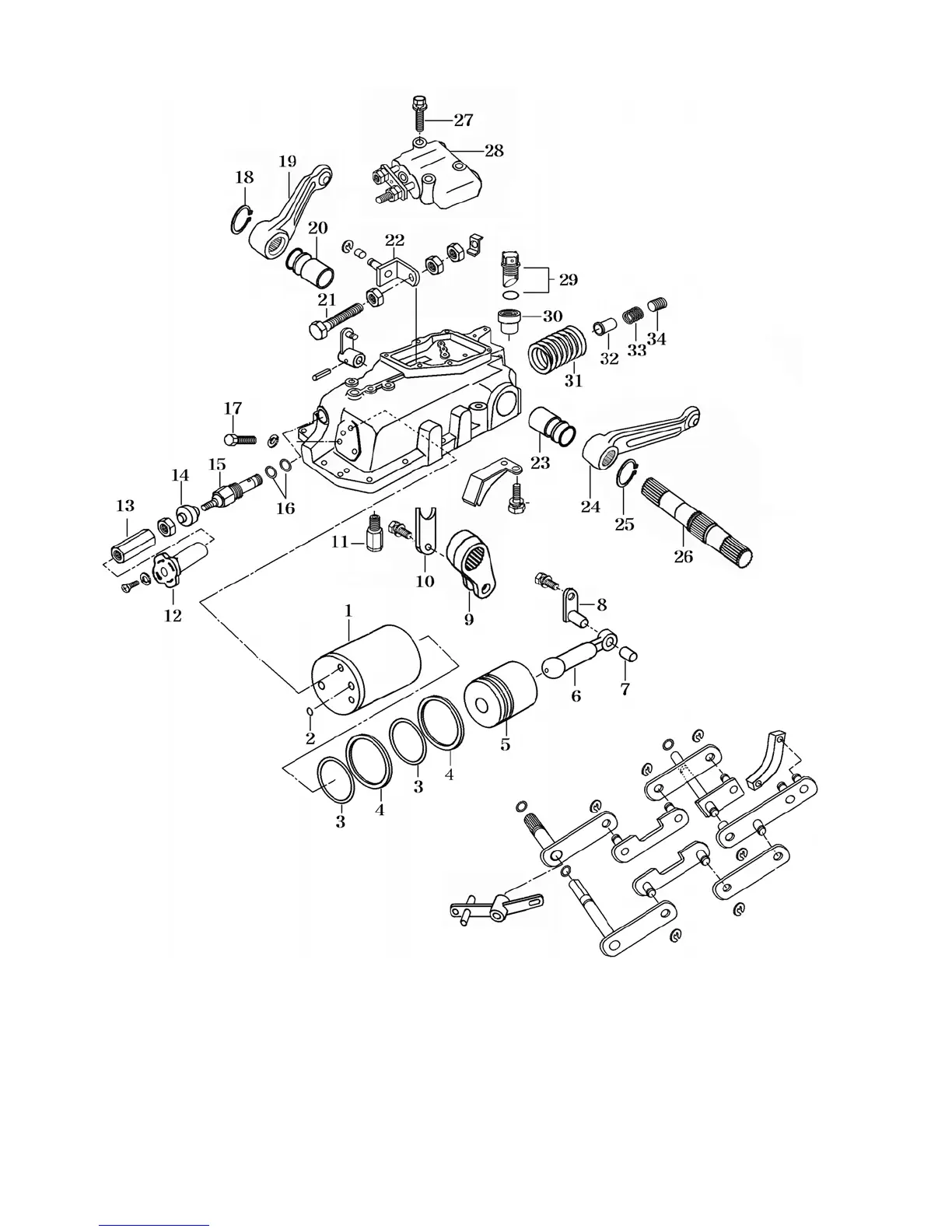
Fig.9-2
1.Cylinder 2. O-ring 3.O-ring 4.Ring 5.Piston,Hyd. 6.Rod piston 7. Bush 8.Pin,Hyd.
9.Lift crank 10.Plate 11.Relief valve 12. Knob 13.Shaft 14.Seal dust
15.Valve flow control 16. O-ring 17.Bolt(M12) 18. C-ring(shaft) 19.Arm,Lift
20. Bush(50X55X44) 21.Bolt(M8X50) 22. Clevis 23. Bush(50X55X44) 24. Arm lift
25.C-ring 26.Bar 27.Bolt(M8X45) 28.Valve,Main control
29.Cap oil 30.Collar(24X38X44) 31.Spring(SC067) 32.Filter
33.Spring 34.Plug PTO