LEA-5, NEO-5, TIM-5H - Hardware Integration Manual
GPS.G5-MS5-09027-A2 Released Design-in
Page 30 of 68
2.3 NEO-5 design
2.3.1 Passive antenna design (NEO-5)
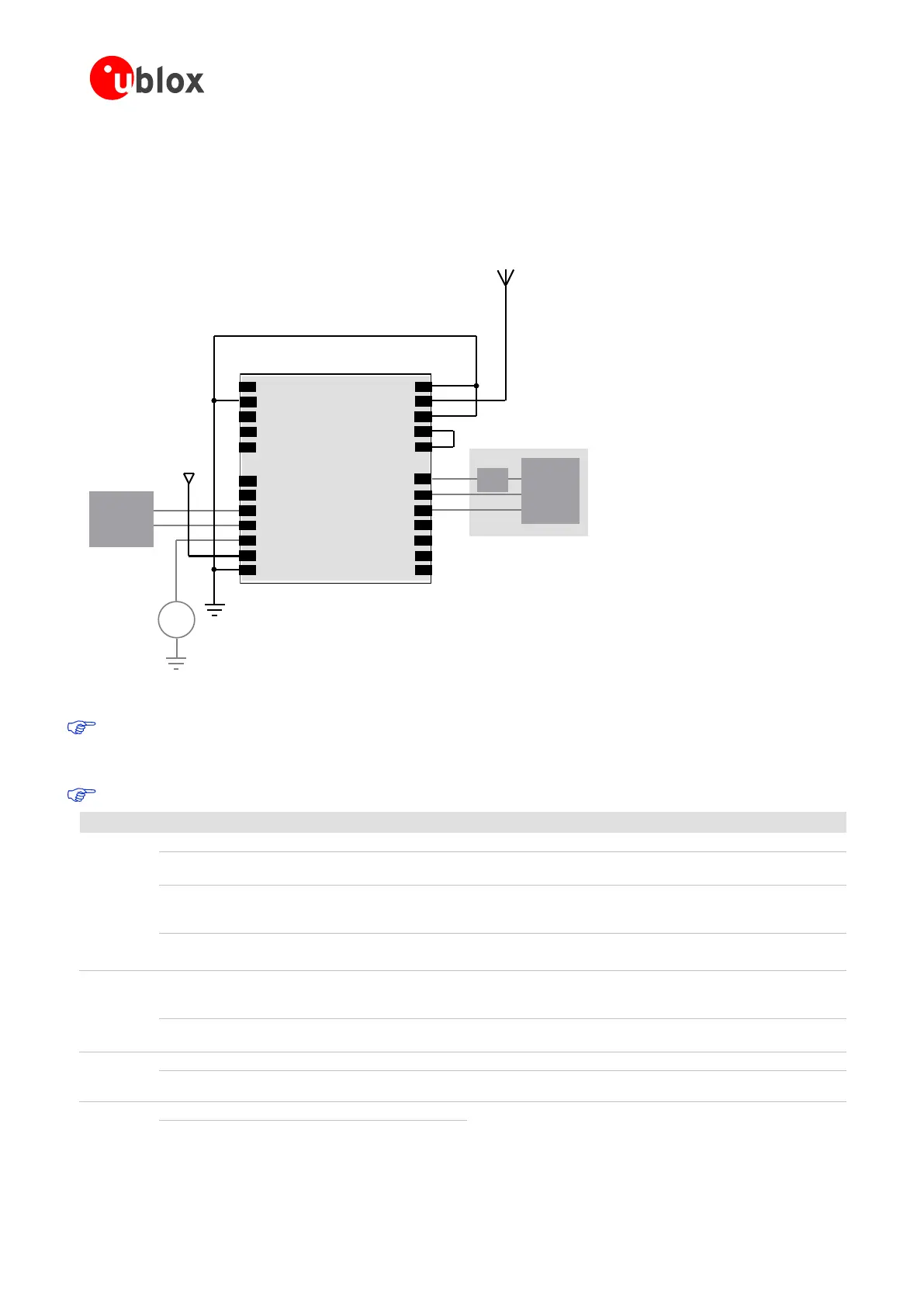
This is a minimal setup for a PVT GPS receiver with a NEO-5 module.
Vcc
Micro
Processor
(serial)
Passive Antenna
Backup
Battery
+
NEO-5
Top View
2
3
4
5
6
8
10
12
24
22
21
20
19
17
15
13
23
GND
Reserved
SS_N/NC
TIMEPULSE
EXTINT0
USB_DM
USB_DP
VDDUSB
Reserved
VCC_RF
GND
GND
RF_IN
GND
VCC
V_BCKP
RxD1
TxD1
SCL2
SDA2
SCS1_N/NC
CFG_GPS0/SCK/NC
MISO/CFGCOM1/NC
MOSI/CFG_COM0
14
16
11
9
7
1
18
USB port (Optional)
Micro
Processor
(USB)
LDO
Figure 16: Passive antenna design for NEO-5 receivers
The above design is for the USB in self-powered mode. For bus-powered mode pin 14 (CFG_COM0)
must be left open and Vcc must be connected to VDDUSB. NMEA baud rate is 38400 when in self-
powered mode.
For passive antenna designs use an LNA to increase sensitivity up to 2dB.
Max allowed ripple on VCC=50mVpp
Assure a good GND connection to all GND pins of the module,
preferably with a large ground plane.
It‖s recommended to connect a backup battery to V_BCKP in order
to enable Warm and Hot Start features on the receivers. Otherwise
connect to GND (or VCC).
To use the USB interface connect this pin to 3.0 – 3.6V.
If no USB serial port used connect to GND.
GPS signal
input from
antenna
The connection to the antenna has to be routed on the PCB. Use a
controlled impedance of 50 Ohm to connect RF_IN to the antenna
or the antenna connector.
Output Voltage
RF section
Pins 8 and 9 must be connected together. VCC_RF can also be used
to power an external active antenna.
3.6V tolerant serial input. Internal pull-up resistor to VCC. Leave
open if not used.
USB2.0 bidirectional communication pin. Leave open if unused.
Implementation see Section 1.5.2

 Loading...
