LEA-5, NEO-5, TIM-5H - Hardware Integration Manual
GPS.G5-MS5-09027-A2 Released Hardware description
Page 9 of 68
RF Front-End
with
Integrated LNA
Baseband Processor
Power
Management
TCXO or Crystal
RTC
RF_IN
Digital
IF Filter
Backup
RAM
ROM Code
GPS
Engine
ARM7TDMI-S
®
SRAM
SAW
Filter
RTC
VCC_RF
VCC
V_BACKUP
GND
SPI (optional)
DDC
TIMEPULSE
EXTINT
UART
USB V2.0
CFG
V_RESET
RF Front-End
with
Integrated LNA
Baseband Processor
Power
Management
TCXO
RTC
FLASH Memory
Antenna
Supervision
Power Control
RF_IN
V_ANT
AADET_N
VCC_RF
VCC
V_BACKUP
GND
VCC
_OUT
UART
EXTINT
RESET_N
SAFEBOOT
TIMEPULSE
Digital
IF Filter
Backup
RAM
ROM Code
GPS/GALILEO
Engine
ARM7TDMI-S
®
SRAM
SAW
Filter
RTC
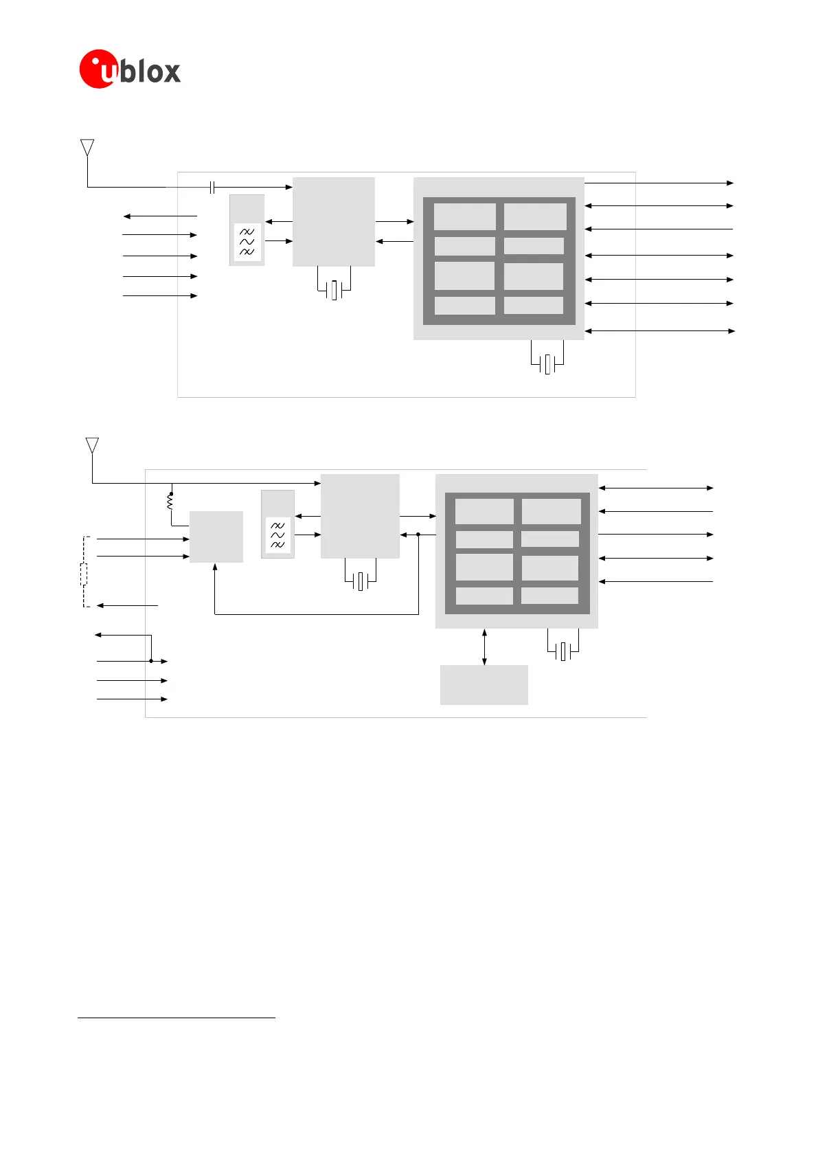
Figure 1: Block diagrams of LEA-5, NEO-5 and TIM-5H modules
1.3 Power management
1.3.1 Connecting power
u-blox 5 receiver modules have up to three power supply pins: VCC, V_BCKP and VDDUSB
.
1.3.1.1 VCC - –ain power
The main power supply is fed through the VCC pin. During operation, the current drawn by the u-blox 5 GPS
module can vary by some orders of magnitude, especially, if low-power operation modes are enabled. It is
important that the system power supply circuitry is able to support the peak power (see datasheet for
Not available with TIM-5H

 Loading...
