USER GUIDE
Control Operation - Service 3
u-line.com
SAFETY • INSTALLATION & INTEGRATION • OPERATING INSTRUCTIONS • MAINTENANCE • SERVICE
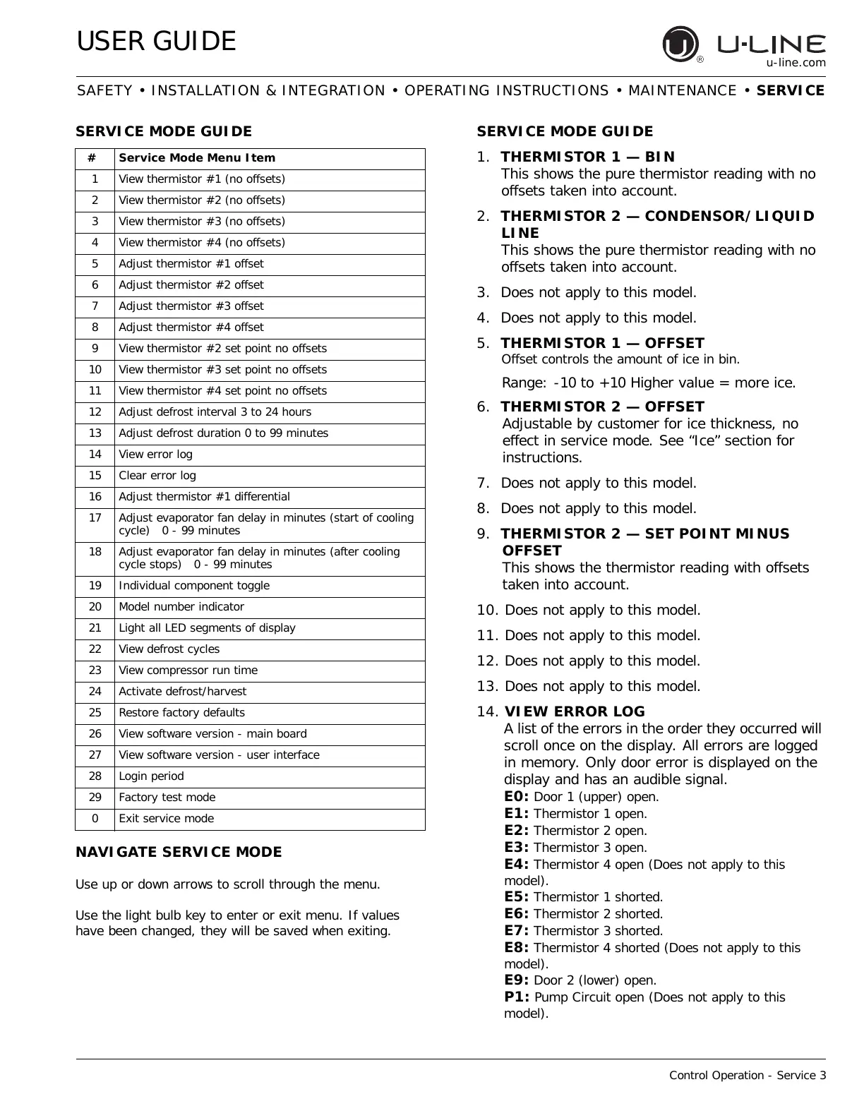
SERVICE MODE GUIDE
1. THERMISTOR 1 — BIN
This shows the pure thermistor reading with no
offsets taken into account.
2. THERMISTOR 2 — CONDENSOR/LIQUID
LINE
This shows the pure thermistor reading with no
offsets taken into account.
3. Does not apply to this model.
4. Does not apply to this model.
5. THERMISTOR 1 — OFFSET
Offset controls the amount of ice in bin.
Range: -10 to +10 Higher value = more ice.
6. THERMISTOR 2 — OFFSET
Adjustable by customer for ice thickness, no
effect in service mode. See “Ice” section for
instructions.
7. Does not apply to this model.
8. Does not apply to this model.
9. THERMISTOR 2 — SET POINT MINUS
OFFSET
This shows the thermistor reading with offsets
taken into account.
10. Does not apply to this model.
11. Does not apply to this model.
12. Does not apply to this model.
13. Does not apply to this model.
14. VIEW ERROR LOG
A list of the errors in the order they occurred will
scroll once on the display. All errors are logged
in memory. Only door error is displayed on the
display and has an audible signal.
E0:
Door 1 (upper) open.
E1: Thermistor 1 open.
E2: Thermistor 2 open.
E3: Thermistor 3 open.
E4: Thermistor 4 open (Does not apply to this
model).
E5: Thermistor 1 shorted.
E6: Thermistor 2 shorted.
E7: Thermistor 3 shorted.
E8: Thermistor 4 shorted (Does not apply to this
model).
E9: Door 2 (lower) open.
P1: Pump Circuit open (Does not apply to this
model).
# Service Mode Menu Item
1 View thermistor #1 (no offsets)
2 View thermistor #2 (no offsets)
3 View thermistor #3 (no offsets)
4 View thermistor #4 (no offsets)
5 Adjust thermistor #1 offset
6 Adjust thermistor #2 offset
7 Adjust thermistor #3 offset
8 Adjust thermistor #4 offset
9 View thermistor #2 set point no offsets
10 View thermistor #3 set point no offsets
11 View thermistor #4 set point no offsets
12 Adjust defrost interval 3 to 24 hours
13 Adjust defrost duration 0 to 99 minutes
14 View error log
15 Clear error log
16 Adjust thermistor #1 differential
17 Adjust evaporator fan delay in minutes (start of cooling
cycle) 0 - 99 minutes
18 Adjust evaporator fan delay in minutes (after cooling
cycle stops) 0 - 99 minutes
19 Individual component toggle
20 Model number indicator
21 Light all LED segments of display
22 View defrost cycles
23 View compressor run time
24 Activate defrost/harvest
25 Restore factory defaults
26 View software version - main board
27 View software version - user interface
28 Login period
29 Factory test mode
0Exit service mode
NAVIGATE SERVICE MODE
Use up or down arrows to scroll through the menu.
Use the light bulb key to enter or exit menu. If values
have been changed, they will be saved when exiting.
SERVICE MODE GUIDE
41
 Loading...