Do you have a question about the U-Line UHNP315-IS02A and is the answer not in the manual?
Procedures for property damage or personal injury related to a U-Line product.
Definitions of safety alert icons: Danger, Warning, and Caution.
Warnings about R600a refrigerant, flammability, and service precautions.
Service must be done by authorized personnel; parts must be like components.
Information on chemicals known to cause cancer and birth defects.
Requirement for adequate backflow protection for installation.
Risk of child entrapment; instructions to remove doors and leave shelves.
Damages from ambient temperatures below 40°F (4°C) are not covered by warranty.
Shock hazard warning; disconnect power before service.
Electrical installation must follow codes; requires grounded, polarized receptacle.
Unit cannot be installed behind a closed cabinet door.
Units must operate from separate, grounded electrical receptacles.
Space requirements for installing two units hinge-by-hinge.
Plumbing must follow codes and be done by licensed contractors.
Do not use plastic water supply lines; they may crack or rupture.
Use new hose set; do not use tape or joint compound on gasketed lines.
Instructions for connecting the drain line based on model type.
Improper drain connections can cause injury or damage; route downward.
Equipment requires adequate backflow protection per codes.
Maximum lift for P60 drain pump is 10 feet; install close to rear of unit.
Instructions for securing the unit to cabinets or countertops.
Instructions for securing the unit to the floor for freestanding applications.
How to use a level to ensure the unit is properly leveled.
Tips for positioning the unit in the cutout opening, especially with uneven floors.
Disconnect electric power before removing or installing the grille.
Do not touch condenser fins; they are sharp and can be easily damaged.
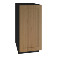
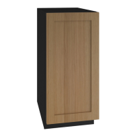
Clearance needed for integrated models adjacent to a wall for 90° door swing.
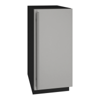
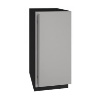
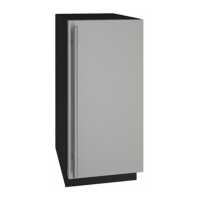
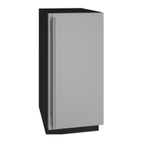
Clearance needed for stainless steel models adjacent to a wall for 90° door swing.
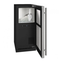
How to align and adjust the door for proper sealing and operation.
Step-by-step instructions for reversing the door swing.
Recommends discarding ice produced during the first 2-3 hours of operation.
Guide to functions, commands, and options for controlling the unit.
Alerts and actions when the door is left open for more than 30 minutes.
Kills and prevents growth of viruses, bacteria, fungi, mold, and mildew.
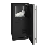
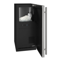
How the machine produces ice and ensures a constant supply.
Instructions on how to adjust the ice density from firm to soft.
Unit requires proper airflow; do not block front grille or install behind a door.
Cleaning instructions for vinyl clad and stainless steel models.
Instructions for cleaning the interior and removed components.
How to perform the automatic clean cycle and recommended intervals.
Disconnect power before cleaning; do not touch condenser fins.
Recommended steps for periods of extended non-use.
Additional steps for winterizing the unit if exposed to low temperatures.
List of service menu options for diagnostics and adjustments.
Common error codes and their meanings.
Steps to program the unit to the correct model number.
Steps to take before contacting service for a malfunctioning product.
Description of common sounds the unit may make.
Table of problems, possible causes, and remedies.
Electrocution and burn hazards; precautions for servicing the unit.
Steps to remove the base assembly for service.
Steps to disassemble the evaporator module.
Warning about the sharp auger; handle with care to avoid injury.
Steps for installing various evaporator module components.
Responsibilities of field service technicians regarding damage assessment and reporting.
Parameters and requirements for filing a warranty claim.
Illustrated parts list for the UHNP315-SS01A model.
Illustrated parts list for the Nugget Ice Evaporator.
Importance of using genuine U-Line replacement parts to avoid damage and voiding warranty.
Flammability warnings for R600a refrigerant.
Requirement for personal protective equipment when servicing.
Procedures for recovering and reclaiming R-600a refrigerant.
Table correlating system conditions with pressure, line, and temperature readings.
Electrocution and burn hazards; precautions for servicing the unit.
Advanced diagnostic capabilities for electronic controls.
Description of common sounds the unit may make.
Flowchart to diagnose issues when the unit does not power on.
Guide for common concerns, potential causes, and actions.
Function of the plunger switch for monitoring door state.
List of error codes and their meanings.
Steps to diagnose and resolve water detection sensor error.
Steps to check for water leaks and sensor issues.
Steps to diagnose and correct float switch errors.
Steps to diagnose and correct float switch errors related to ice production.
Steps to diagnose and resolve drain related errors.
Diagram of UI buttons and their functions.
How to activate and cancel silent mode for temporary shutdowns.
How to enter and exit showroom mode for display purposes.
How to enter and navigate the service mode for diagnostics.
Reading for the bin thermistor.
Adjusts the amount of ice in the bin.
How to view logged error codes.
Procedure to clear logged errors.
Testing individual components by toggling them on/off.
Displays the two-digit model number of the unit.
Steps to program the unit to its correct model number.
Information about the evaporator thermistor and its function.
Table of thermistor resistance values at different temperatures.
How thermistor failure affects unit operation.
Coverage and terms for the one-year limited warranty.
Coverage and terms for the two-year limited warranty for 5 Class products.
Coverage and terms for the five-year limited warranty on sealed system parts.
| Product Type | Ice Maker |
|---|---|
| Power Source | Electric |
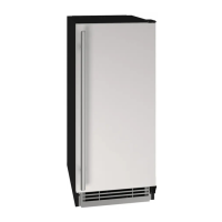
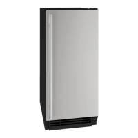
| Finish | Stainless Steel |
| Door Style | Solid |
| Drain Type | Gravity Drain |
| Condenser Type | Air Cooled |
| Clear Ice Technology | Yes |
| Voltage | 115V |
| Housing Material | Stainless Steel |
| Height | 34 in |
| Electrical Requirements | 115V/60Hz |