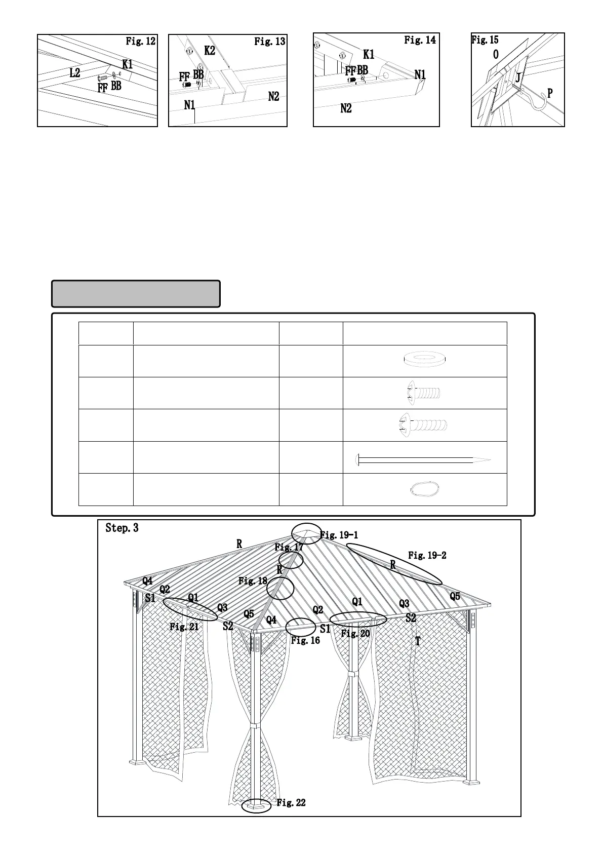
Fig. 12: Attach top short beam 1 / top short beam 2 (L1/L2) to the slanted beam (K1) with screws (FF) and washers (BB).
Then attach top middle beam 1/ top middle beam 2 (M1/M2) to the slanted beam (K1) and middle beam (K2) with screws
(FF) and washers (BB) as shown.
Fig. 13: Attach top long beam 1/ top long beam 2 (N1 /N2) to the middle beam (K2) with screws (FF) and washers (BB).
Fig. 14: Attach top long beam 1/ top long beam 2 (N1 /N2) to the slanted beam (K1) with screws (FF) and washers (BB).
Fig. 15: Place the big top cover (O) onto the top connector (J) and, then screw the hook (P) to the big top cover (O). Do not
fully tighten bolts at this stage.