SARA-R4 series - System integration manual
UBX-16029218 - R20 Design-in Page 86 of 128
C1-Public
Providing the TXD and RXD lines only
☞ Providing the TXD and RXD lines only is not recommended if the multiplexer functionality is used
in the application: providing also at least the HW flow control (RTS and CTS lines) is recommended,
and it is in paricular necessary if the low power mode is enabled by +UPSV AT command.
If functionality of the CTS, RTS, DSR, DCD, RI and DTR lines is not required in the application, then:
• Connect the RTS input line to GND or to the CTS output line of the module, since the module
requires RTS active (low electrical level) if HW flow-control is enabled (AT&K3, default setting)
• Connect the DTR input line to GND using a 0 series resistor, because it is useful to set DTR active
if not specifically handled, in particular to have URCs presented over the UART interface (see
SARA-R4 series AT commands manual [2], &D, S0, +CNMI AT commands)
• Leave DSR, DCD and RI lines of the module floating
If RS-232 compatible signal levels are needed, the Maxim MAX13234E voltage level translator can be
used. This chip translates voltage levels from 1.8 V (module side) to the RS-232 standard.
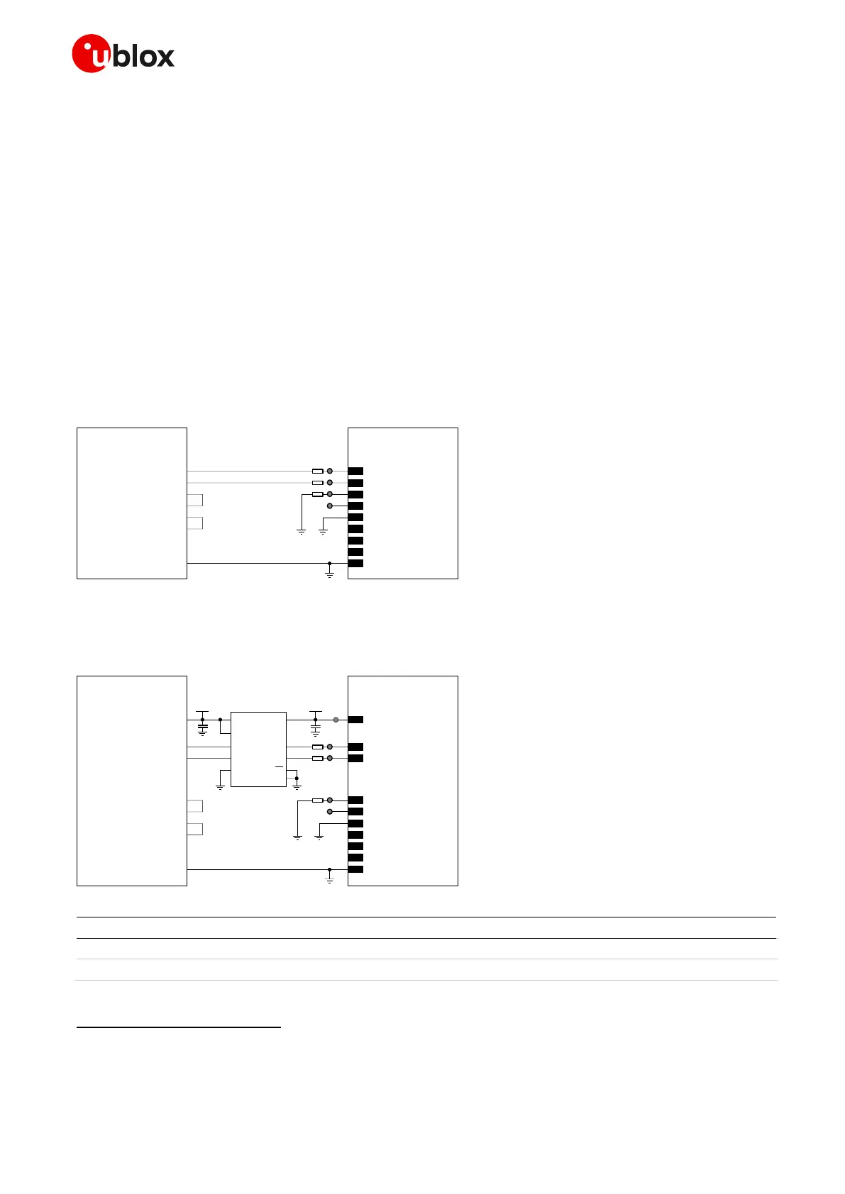
If a 1.8 V Application Processor (DTE) is used, the circuit that should be implemented as in Figure 57.
Figure 57: UART interface application circuit with a 3-wire link in the DTE/DCE serial communication (1.8V DTE)
If a 3.0 V Application Processor (DTE) is used, then it is recommended to connect the 1.8 V UART
interface of the module (DCE) by means of appropriate unidirectional voltage translators using the
module V_INT output as 1.8 V supply for the voltage translators on the module side, as in Figure 58.
Flow control is not supported by SARA-R410M-01B and SARA-R410M-02B-00 product versions. The RTS input must be set low to
communicate over UART on SARA-R410M-01B product version. The DTR input must be set low to have URCs presented over UART on
SARA-R410M-01B and SARA-R41xM-x2B product versions.
 Loading...


