EasyManuals Logo

Ublox SARA-R42 User Manual

Ublox SARA-R42
128 pages
To Next Page IconTo Next Page
To Previous Page IconTo Previous Page
Page #99 background imageLoading...
Page #99 background image
SARA-R4 series - System integration manual
UBX-16029218 - R20 Design-in Page 99 of 128
C1-Public
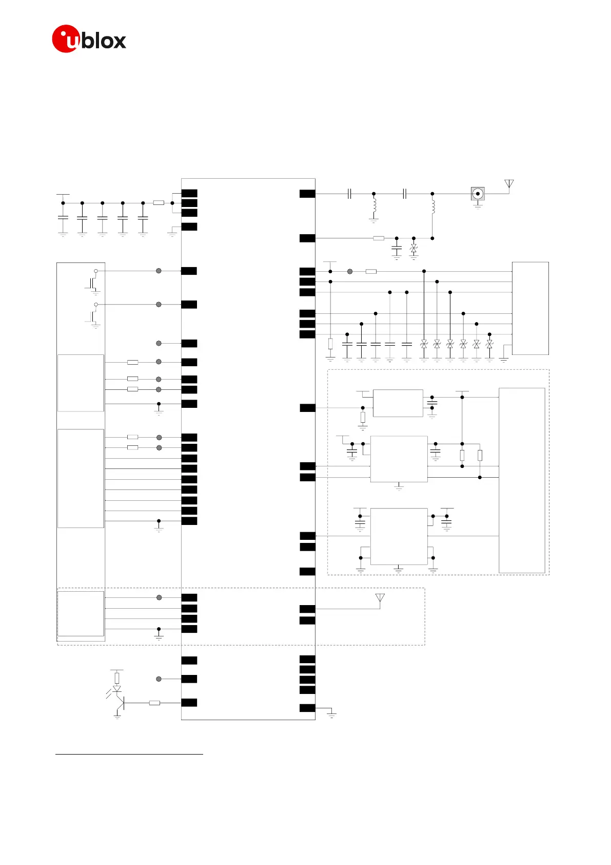
2.14 Schematic for SARA-R4 series module integration
2.14.1 Schematic for SARA-R4 series modules
Figure 68 is an example of a schematic diagram where a SARA-R4 series module is integrated into an
application board using almost all available interfaces and functions.
3V8
GND
100uF 10nF
SARA-R4 series
52 VCC
53 VCC
51 VCC
68pF
18 RESET_N
Application
Processor
Open
drain
output
15 PWR_ON / PWR_CTRL
Open
drain
output
TP
TP
12
TXD
13
RXD
8
DCD
10
RTS
11
CTS
9
DTR
6
DSR
7
RI
TP
TP
TXD
RXD
DCD
RTS
CTS
DTR
DSR
RI
1.8 V DTE
GND GND
USB 2.0 host
D-
D+
28
USB_D-
29
USB_D+
VBUS 17
VUSB_DET / USB_5V0
TP
TP
GND GND
0Ω
0Ω
0Ω
0Ω
47pF
SIM Card
Holder
VCC (C1)
VPP (C6)
IO (C7)
CLK (C3)
RST (C2)
GND (C5)
47pF47pF 100nF
41VSIM
39SIM_IO
38SIM_CLK
40SIM_RST
47pF
SW1
SW2
4V_INT
42GPIO5
470k
ESD ESD ESD ESD ESD ESD
1k
TP
V_INT
62ANT_DET
10k
27pF
ESD
68nH
56
Connector
Cellular
antenna
33pF
ANT
TP
0Ω
39nH
15pF
15pF100nF
24GPIO3
V_INT
B1 A1
GND
B2 A2
VCCB VCCA
SN74AVC2T245
Voltage Translator
100nF
100nF
3V0
TxD1
4.7k
IN
OUT
LDO Regulator
SHDNn
4.7k
3V8 3V0
23GPIO2
V_INT
SDA_A
SDA_B
GND
SCL_A
SCL_B
VCCA
VCCB
TCA9406
I2C Voltage Translator
100nF
100nF
100nF
47k
SDA2
SCL2
VCC
DIR1
DIR2OEn
OE
GND
EXTINT0GPIO4 25
u-blox GNSS
3.0 V receiver
26SDA
27SCL
Not supported by SARA-R410M-01B /-R422 /-R422M8S
19GPIO6
GND
3V8
Network
Indicator
16
GPIO1
36I2S_CLK / SPI_CLK
34I2S_WA / SPI_MOSI
35I2S_TXD / SPI_CS
37I2S_RXD / SPI_MISO
Ferrite
Bead
2
USB_3V3
TP
RSVD
TP
RSVD33
31ANT_GNSS
GNSS
antenna
44ANT_ON
46
EXTINT
47
TXD_GNSS
45
TIMEPULSE
Output
RXD
Input
GND GND
SARA-R422M8S
only
TP
Figure 68: Example of schematic diagram to integrate a SARA-R4 series module using all available interfaces
44
44
Flow control is not supported by SARA-R410M-01B and SARA-R410M-02B-00 product versions. The RTS input must be set low to
communicate over UART on SARA-R410M-01B product version. The DTR input must be set low to have URCs presented over UART on
SARA-R410M-01B and SARA-R41xM-x2B product versions.

Table of Contents

Other manuals for Ublox SARA-R42

Questions and Answers:

Question and Answer IconNeed help?

Do you have a question about the Ublox SARA-R42 and is the answer not in the manual?

Ublox SARA-R42 Specifications

General IconGeneral
BrandUblox
ModelSARA-R42
CategoryControl Unit
LanguageEnglish

Related product manuals