SARA-R42 - Application note
UBX-20050829 - R02 AT commands response parser Page 13 of 58
C1-Public
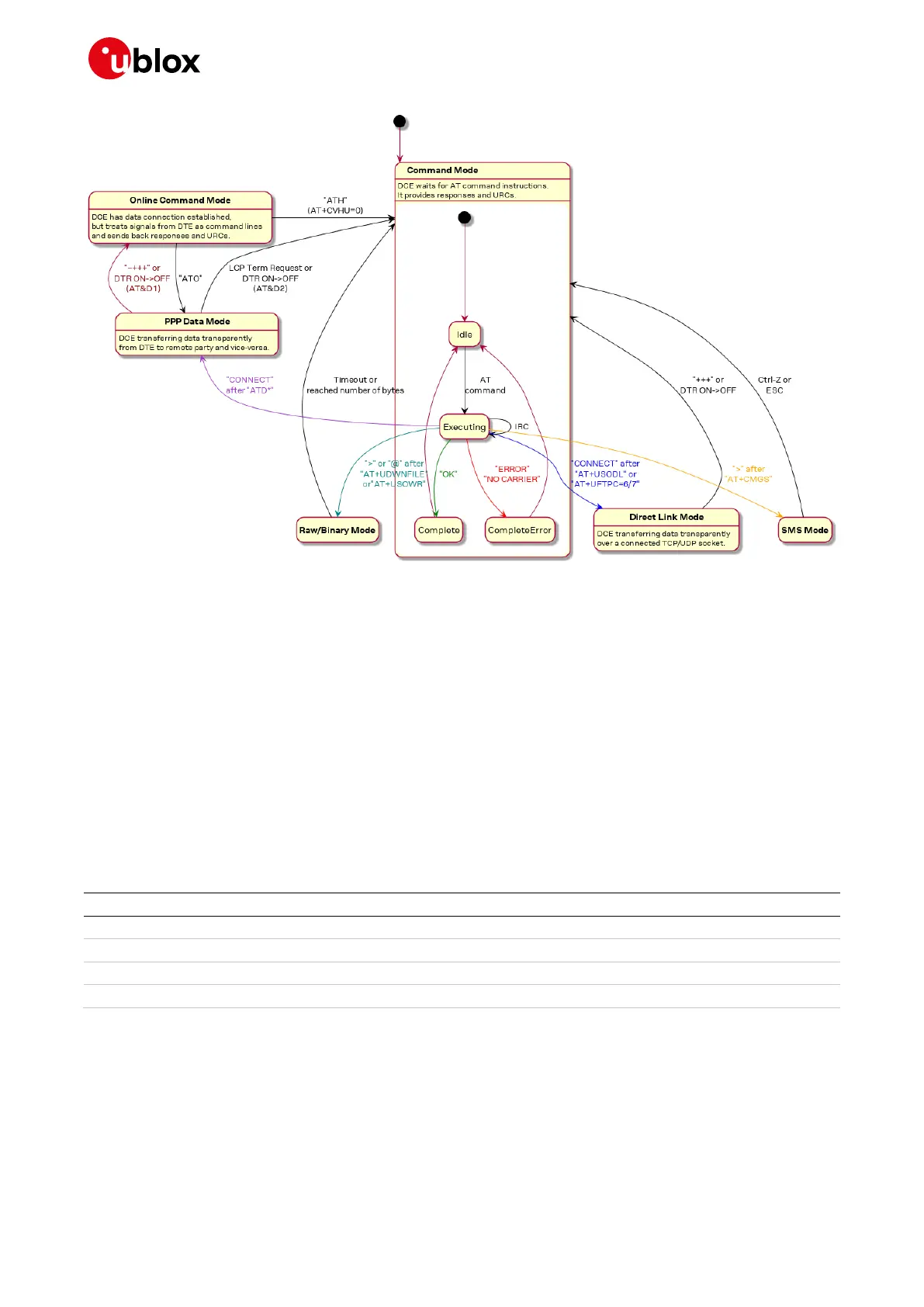
Figure 2: Module operating modes and actions causing mode transitions
4.2 Unsolicited result code
An unsolicited result code (URC) is a string message (provided by the DCE) that asynchronously
indicates the occurrence of an event that might be related to a previous AT command or to the feature
the user is currently using, or to the module’s autonomous activity (for example, due to mobility).
When enabled on a given AT port, the URC can be output at any time to report a specific event or
status change on the same AT port. If the AT port is busy, the application can decide to discard +CIND,
+CGEV and SMS related URC by properly configuring the related AT commands; all other URCs will be
deferred and printed when the AT port returns into command mode.
☞ Due to race conditions in mode transitions, URC can be received after an AT command has been
transmitted by the host application.
Examples of some URCs are shown in Table 2.
+CEREG: <stat>[,<tac>,<ci>,<AcT>]

 Loading...


