SARA-R4 series - System integration manual
UBX-16029218 - R20 System description Page 24 of 128
C1-Public
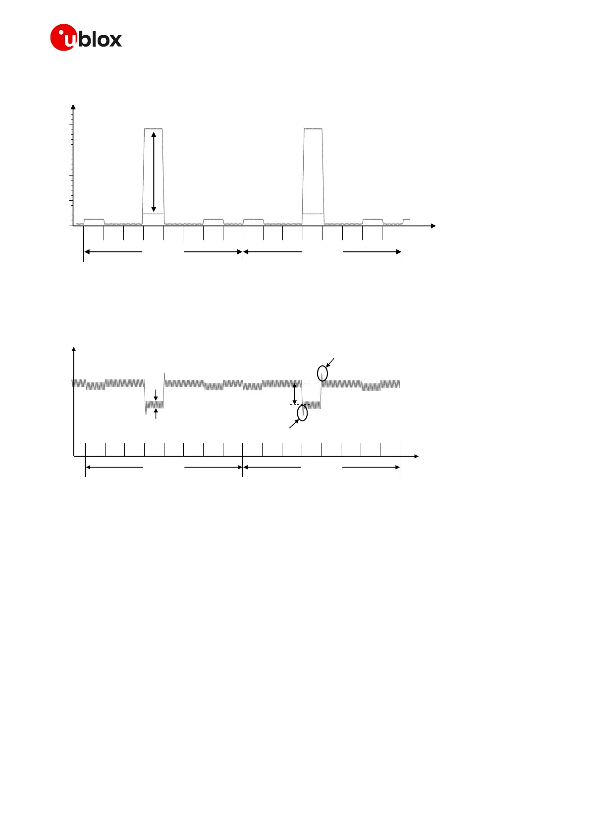
Figure 8 shows an example of the module current consumption profile versus time in 2G single-slot.
Figure 8: VCC current consumption profile versus time during a GSM call (1 TX slot, 1 RX slot)
Figure 9 illustrates the VCC voltage profile versus time during a 2G single-slot call, according to the
related VCC current consumption profile described in Figure 8.
Figure 9: Description of the VCC voltage profile versus time during a 2G single-slot call (1 TX slot, 1 RX slot)
When a GPRS connection is established, more than one slot can be used to transmit and/or more than
one slot can be used to receive. The transmitted power depends on network conditions, which set the
peak current consumption. But according to GPRS specifications, the maximum transmitted RF
power is reduced if more than one slot is used to transmit, so the maximum peak of current is not as
high as it can be in the case of a GSM call.
If the module transmits in GPRS multi-slot class 12, in 850 or 900 MHz bands, at maximum RF power
level, the consumption can reach a quite a high peak but lower than the one achievable in 2G single-
slot mode. This happens for 2.308 ms (width of the 4 Tx slots/bursts) in the case of multi-slot class
12, with a periodicity of 4.615 ms (width of 1 frame = 8 slots/bursts), so with a 1/2 duty cycle,
according to GSM TDMA.
If the module is in GPRS connected mode in the 1800 or 1900 MHz bands, consumption figures are
lower than in the 850 or 900 MHz band because of the 3GPP Tx power specifications.
 Loading...


