SARA-R4 series - System integration manual
UBX-16029218 - R20 System description Page 30 of 128
C1-Public
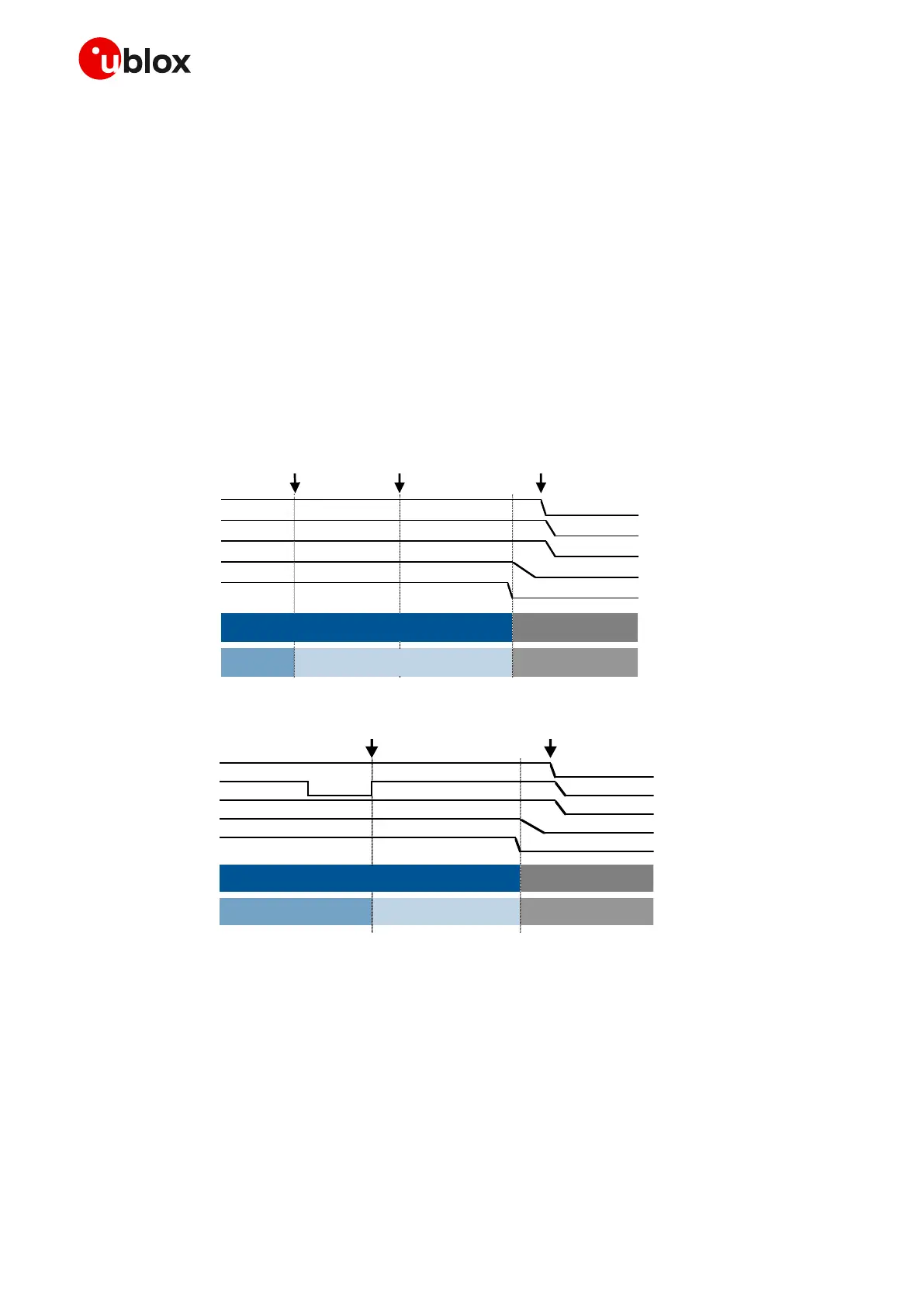
Figure 15 and Figure 16 describe the SARA-R4 series modules switch-off sequence started by means
of the AT+CPWROFF command and by means of the PWR_ON / PWR_CTRL input pin respectively,
allowing storage of current parameter settings in the module’s non-volatile memory and a clean
network detach, with the following phases:
• When the +CPWROFF AT command is sent, or when a low pulse with appropriate time duration
(see the SARA-R4 series data sheet [1]) is applied at the PWR_ON / PWR_CTRL input pin, the
module starts the switch-off routine.
• Then, if the +CPWROFF AT command has been sent, the module replies OK on the AT interface:
the switch-off routine is in progress.
• At the end of the switch-off routine, all the digital pins are tri-stated and all the internal voltage
regulators are turned off, including the generic digital interfaces supply (V_INT).
• Then, the module remains in switch-off mode as long as a switch on event does not occur (e.g.
applying a low level to PWR_ON / PWR_CTRL input pin), and it enters not-powered mode if the
VCC supply is removed.
Figure 16: SARA-R4 series modules switch-off sequence by means of PWR_ON / PWR_CTRL pin
☞ The Internal Reset signal is not available on a module pin, but it is highly recommended to monitor
the V_INT pin to sense the end of the switch-off sequence.
⚠ VCC supply can be removed only after V_INT goes low: an abrupt removal of the VCC supply during
SARA-R4 series modules normal operations may lead to an unrecoverable faulty state!
☞ The duration of each phase in the SARA-R4 series modules’ switch-off routines can largely vary
depending on the application / network settings and the concurrent module activities.
 Loading...


