SARA-R4 series - System integration manual
UBX-16029218 - R20 Design-in Page 73 of 128
C1-Public
In-band interference
In-band interference signals are typically caused by harmonics from displays, switching converters,
micro-controllers and bus systems. Moreover, considering for example the LTE band 13 high channel
transmission frequency (787 MHz) and the GPS operating band (1575.42 MHz ± 1.023 MHz), the
second harmonic of the cellular signal is exactly within the GPS operating band. Therefore, depending
on the board layout and the transmit power, the highest channel of LTE band 13 is the channel that
has the greatest impact on the C/No reduction.
Countermeasures against in-band interference include:
• maintaining a good grounding concept in the design
• ensuring proper shielding of the different RF paths
• ensuring proper impedance matching of RF traces
• placing the GNSS antenna away from noise sources
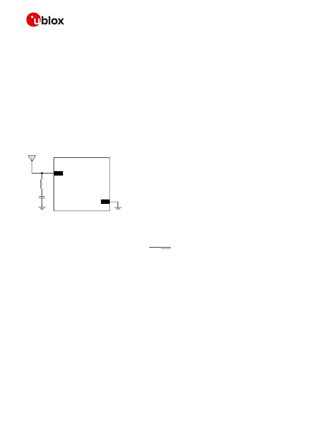
• add a notch filter along the GNSS RF path, just after the antenna, at the frequency of the jammer
(as for example illustrated in Figure 44)
Figure 44: Simple notch filter for improved in-band jamming immunity against a single jamming frequency
With reference to Figure 44, a simple notch filter can be realized by the series connection of an
inductor and capacitor. Capacitor C1 and inductor L1 values are calculated according to the formula:
𝑓 =
1
2 𝜋
√
𝐶 ⋅ 𝐿
For example, a notch filter at ~787 MHz improves the GNSS immunity to LTE band 13 high channel.
Suitable component nominal values are C1 = 3.3 pF and L1 = 12 nH, with tolerance less than or equal
to 2 % to ensure adequate notch frequency accuracy.
Out-of-band interference
Out-of-band interference is caused by signal frequencies that are different from the GNSS, the main
sources being cellular, Wi-Fi, bluetooth transmitters, etc. For example, the lowest channels in LTE
band 3, 4 and 66 can compromise the good reception of the GLONASS satellites. Again, the effect can
be explained by comparing the LTE frequencies (low channel transmission frequency is 1710 MHz)
with the GLONASS operating band (1602 MHz ± 8 MHz). In this case the LTE signal is outside the
useful GNSS band, but provided that the power received by the GNSS subsystem at 1710 MHz is high
enough, blocking and leakage effects may appear reducing once again the C/No.
Countermeasures against out-of-band interference include:
• maintaining a good grounding concept in the design
• keeping the GNSS and cellular antennas more than the quarter-wavelength (of the minimum Tx
frequency) away from each other. If for layout or size reasons this requirement cannot be met,
then the antennas should be placed orthogonally to each other and/or on different side of the PCB.
 Loading...


