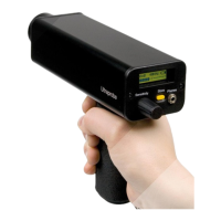
A. PLUG-IN MODULES
TRISONIC
TM
SCANNING MODULE:
This module is utilized to receive air-borne ultrasound such as the ultrasounds emitted by pressure/vacuum leaks and electrical
discharges. There are four prongs at the rear of the module. For placement, align the prongs with the four corresponding jacks in the
front end of the pistol housing and plug in. The Trisonic
TM
Scanning Module has a phased array of three piezoelectric transducers to
pick up the airborne ultrasound. This phased array focuses the ultrasound on one "hot spot" for
directionality and effectively intensifies the signal so that minute ultrasonic emissions can be detected.
STETHOSCOPE (CONTACT) MODULE:
This is the module with the metal rod. This rod is utilized as a "waveguide" in that it is sensitive to ultrasound that is generated
internally such as within a pipe, bearing housing or steam trap. Once stimulated by ultrasound, it transfers the signal to a piezoelectric
transducer located directly in the module housing. It is module shielded to provide protection from stray RF waves that have a
tendency to effect electronic receiving and measurement. This module can be effectively utilized in practically any environment
ranging from airports to broadcasting towers. It is equipped with low noise amplification to allow for a clear, intelligible signal to be
received and interpreted. For placement align the four prongs on the back with the corresponding receptacles in the front of the pistol
and plug in.
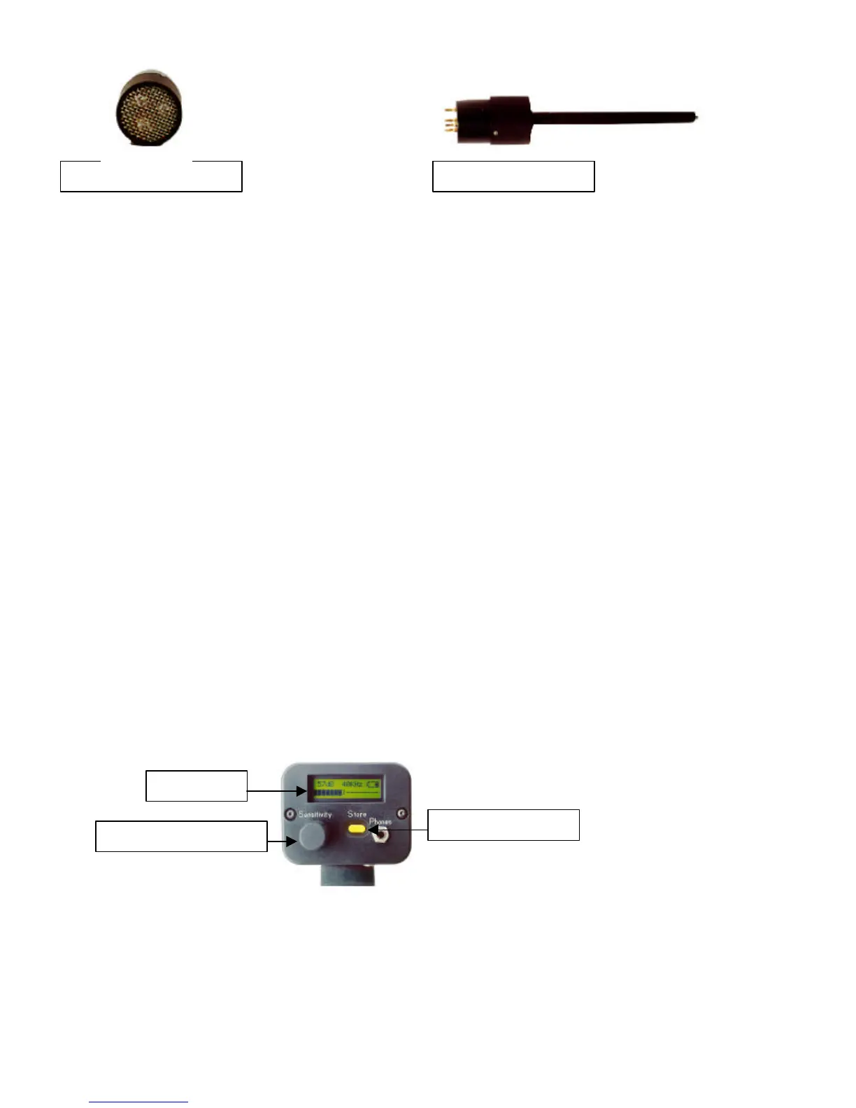
B. PISTOL-GRIP HOUSING
DISPLAY PANEL:
In the Operation Mode the Display Panel will show intensity levels (as dB and as a bar graph), Frequency, Battery Level, and
“Display Mode”. The Display Mode and the Battery level indications alternate. Intensity levels are shown simultaneously as a
numeric dB value and on a sixteen segmented bar graph (with each segment representing 3 dB). The Frequency is adjustable from 20
kHz to 100 kHz. These represent the range of frequency selection capable with the Ultraprobe. The most common frequency used for
general leak detection or electrical inspection is 40 kHz. These frequencies may be "tuned in" when performing inspections with any
of the Ultraprobe’s plug-in modules. The Display Mode indicates the operation mode of the instrument. This is indicated on the
display panel as R for Real Time, P for Peak Hold, S for Snap Shot, or RO for Real Time “Offset”, PO for Peak Hold “Offset” and
SO for Snap Shot “Offset”. (For additional information about Offset see dB Scale Select in the Set Up Mode Section..
Trisonic Scanning Module Stethoscope Module
Sensitivity Control Dial
Storage Entry Button
Display Panel
 Loading...