Do you have a question about the UNI-T UDP3305S Series and is the answer not in the manual?
Introduction to the user manual and safety notes.
Uni-Trend's warranty terms and limitations for the product.
Ownership and rights of Uni-Trend Technology (China) Co., Ltd.
Details on the product's warranty period and service conditions.
Exclusions from warranty coverage and UNI-T's responsibilities.
General guidelines to avoid electric shock and personal injury.
User's responsibility for following safety information and UNI-T's liability.
Importance of proper grounding to prevent electric shock.
Ensuring main supply is within the rated operating range.
Checking product symbols and matching load switch with power source.
Checking test leads for damage to prevent hazards.
Using only specified fuses for the product.
Protecting the product from excessive voltage, including lightning.
Prohibition of opening the instrument case or altering internal circuits.
Avoiding contact with exposed connectors or live components.
Warnings against using the instrument in hazardous environments.
Explanation of the grounding symbol.
Explanation of the protective grounding symbol.
Explanation of the signal grounding symbol.
Explanation of the danger symbol.
Explanation of the power on symbol.
Explanation of the power off symbol.
Explanation of the ground terminal for chassis symbol.
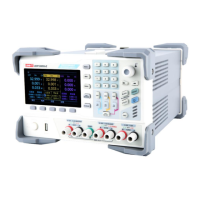
Overview of UDP3305S and UDP3305S-E models and their output ranges.
Description of the front panel layout and controls.
Description of the rear panel connectors and interfaces.
UDP3305S series includes UDP3305S and UDP3305S-E models with output ranges.
Highlights maximum power and individual channel controllability.
Lists four-channel independent output, multi-protection, and independent switches.
Table detailing voltage and current output ratings for different channels.
Specifications for power supply regulation, ripple, and response time.
Specifications for output range, regulation, and ripple current.
Specifications related to parallel and series connections, and tracking error.
Details on display, programming resolution, and accuracy.
Specifies the rise and fall times for voltage programming across channels.
Details the temperature coefficient for voltage and current outputs per °C.
Voltage and current specifications for the USB output.
Diagram and labels for the front panel layout and controls.
Explanation of the function of each key on the front panel.
Detailed descriptions of the functions of various keys and controls.
Diagram and labels for the rear panel connectors and interfaces.
List of accessories included with the power supply and check procedures.
Specifies voltage, frequency, power, and fuse requirements for operation.
General environmental requirements for operating temperature, humidity, etc.
Instructions for cleaning the instrument safely.
Steps for safely powering on the instrument and connecting power.
Description and explanation of the output terminals and indicators.
Introduction to the user interface layout.
Detailed explanation of the elements displayed on the user interface.
Explanation of the constant voltage output mode.
Explanation of the constant current output mode.
How to connect channels in series or parallel.
Introduction to list mode and delayer functions.
Overview of advanced features.
How to configure display settings.
How to save and load settings.
How to configure system parameters.
Step-by-step guide to setting up constant voltage output.
Methods for setting voltage and current values.
How to set and enable/disable protection features.
Steps to turn on the output and check the mode.
Step-by-step guide to setting up constant current output.
How to verify constant current mode and switch if necessary.
Explanation of series and parallel connections for higher voltage/current.
Details on how to perform series connections between channels.
Step-by-step guide for series connection setup.
Details on how to perform parallel connections between channels.
Step-by-step guide for parallel connection setup.
Steps to enter timer/delayer mode and select channels.
How to manually set list mode parameters.
How to set list mode parameters using templates.
How to manually set delayer parameters.
How to set delayer parameters using templates.
Description of the sine waveform template.
Description of the pulse waveform template.
Description of the ramp waveform template.
Description of the stair up waveform template.
Description of the stair down waveform template.
Description of the stair up down waveform template.
Description of the exponential rise waveform template.
Description of the exponential fall waveform template.
Template for controlling output terminal On/Off states.
Template for setting fixed output on/off times.
Template for increasing delay time by a specified step.
Template for declining delay time by a specified step.
How to save list mode, delayer, and state file settings.
Interface for saving and reading list mode files.
Interface for saving and reading delayer files.
Steps to recall saved parameter groups.
Description of displaying voltage, current, and power waveforms.
Operation steps to view waveforms, including list mode and delayer.
Overview of the 5 sets of editable output presets.
Steps to select, edit, and load preset groups.
How the monitor function tracks output and provides alarms.
Steps to enter and configure the monitor interface.
Using the trigger for signal output or controlling instrument output.
Steps to configure trigger input parameters.
Steps to configure trigger output parameters.
Overview of system settings like IP, baud rate, brightness.
Information on software and bootloader versions.
Contact information for UNI-TREND TECHNOLOGY (CHINA) CO., LTD.
| Model | UDP3305S Series |
|---|---|
| Category | Power Supply |
| Output Channels | 3 |
| Output Current Range | 0-5A |
| Resolution | 1mV/1mA |
| Operating Temperature | 0°C to 40°C |
| Display | LCD |
| Interface | USB, RS232 |
| Protections | OVP, OCP, OTP |