Do you have a question about the UNI-T UT30C and is the answer not in the manual?
| Data hold | Yes |
|---|---|
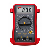
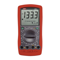
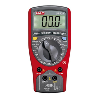
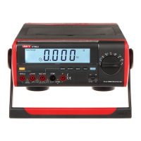
| Product type | Digital multimeter |
| AC voltage range | 200 - 500 V |
| DC current range | 0.02 - 10 A |
| DC voltage range | 0.2 - 500 V |
| Basic accuracy (DC current) | ±(1%+2) |
| Basic accuracy (DC voltage) | ±(0.5%+2) |
| Basic accuracy (resistance) | ±(0.8%+2) |
| Temperature measurement range | -40 - 1000 °C |
| Dimensions (WxDxH) | 74 x 41 x 130 mm |
| Battery voltage | 9 V |
| Weight | 160 g |
|---|
Ensure case is closed, test leads insulated, and battery indicator is monitored.
Set correct function/range, avoid turning switch during measurement, and be cautious with higher voltages.
Replace fuse correctly, avoid humid/hot storage, and clean with mild detergent.
Meter designed for stated voltages. Use prescaler if voltages may be exceeded.
Describes COM, V/ohm/mA, 10A MAX terminals and fuse specifications.
Details maximum display, update rate, and how over-range conditions are shown.
Operating/storage temp, humidity, battery type, and low battery indication.
Specifies the meter's dimensions and approximate weight without test leads.
Details DC voltage ranges, resolution, and accuracy for different models.
Specifies input impedance and overload protection for DC voltage measurements.
Details AC voltage ranges, resolution, and accuracy for different models.
Specifies input impedance, frequency response, and overload protection for AC voltage.
Details DC current ranges, resolution, and accuracy for different models.
Describes overload protection, fuse type, and voltage drop for DC current measurements.
Details AC current ranges, resolution, and accuracy specifically for the UT30F model.
Specifies overload protection, time limits, and frequency response for AC current.
Details resistance ranges, resolution, and accuracy for different models.
Specifies the overload protection for all resistance measurement ranges.
Details temperature ranges, resolution, and accuracy for the UT30C model.
Specifies overload protection and the type of temperature transducer used.
Details frequency measurement range, resolution, accuracy, and input sensitivity for UT30F.
Describes the square wave output function, its frequency, and voltage characteristics for UT30D.
Details diode test function, voltage drop approximation, and conditions.
Details transistor hFE test and continuity beeper test specifications and conditions.
Description of the Liquid Crystal Display and data hold/backlight button.
Details the Rotary Switch and various input jacks for measurement.
Explanation of how to activate and the automatic shut-off for the backlight function.
Instructions on setting the rotary switch and understanding LCD warnings for low battery and input jacks.
Diagram illustrating the setup for measuring DC voltage.
Guidelines on not exceeding 500V, and how to select ranges for unknown values.
Information on handling overload conditions and the effect of input impedance on measurements.
Diagram illustrating the setup for measuring AC voltage.
Notes that AC voltage measurement is the same as DC voltage measurement.
Warning against measuring voltage between open voltage and earth exceeding safety voltage 60V.
Diagram illustrating the setup for measuring DC current.
Instructions for cutting power, inspecting terminals, and setting ranges before measuring current.
Guidance on fuse replacement, non-fused 10A jack, and measurement time intervals.
Diagram illustrating the setup for measuring AC current on the UT30F.
Notes that AC current measurement is the same as DC current measurement.
Safety measures for resistance measurement, including cutting power and checking capacitors.
Guidance on accounting for test lead tolerance and display stabilization for resistance readings.
Diagram illustrating the setup for measuring resistance.
Safety steps for diode measurement, including cutting power and checking capacitors.
How to interpret readings for silicon semiconductor structures and open circuits during diode tests.
Diagram illustrating the setup for measuring diode characteristics.
Checking transistor type (PNP/NPN) and connecting it to the correct jacks.
Details on how the LCD displays hFE value and the measuring conditions (Ibo, Vce).
Diagram illustrating the setup for measuring transistor hFE.
How to connect the K type thermocouple and read temperature in °C.
Information on the temperature probe's limit and alternative thermocouples for higher measurements.
Diagram illustrating the setup for temperature measurement.
Guidelines on output terminal voltage limits and the fixed frequency of 50Hz.
Information on output voltage under load and its use in repairing audio equipment.
Diagram illustrating the setup for square wave output.
Warning against inputting over 230V RMS and advice on using an external attenuator for accuracy.
Guidance on using shielded cables for high frequency signals in noisy environments.
Diagram illustrating the setup for frequency measurement.
Steps to prepare the meter for fuse or battery replacement, including turning off and removing leads.
Instructions for opening the case, replacing the battery/fuse, and reassembling.
Diagram illustrating the process of fuse and battery replacement.
Lists the items included with the multimeter: operating manual, test leads, and thermocouple (for UT30C).