Do you have a question about the UNI-T UT39C and is the answer not in the manual?
Check package contents for missing or damaged parts.
Meter complies with IEC61010 standards, CAT I/II overvoltage, double insulation.
Defines Warning for hazards and Note for attention points.
Inspect case and test leads for damage before use.
Adhere to rules for safe operation, avoid overvoltage, use proper terminals.
Explains symbols like battery deficiency, AC/DC, warning, grounding, diode, continuity, fuse.
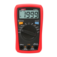
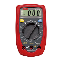
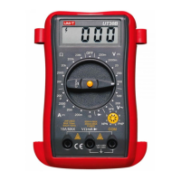
Identifies parts like LCD Display, buttons, terminals, and rotary switch.
Describes how to turn the meter on and off using the POWER button.
Explains entering and exiting hold mode, and display of 'H'.
Lists meanings of symbols like Data Hold, negative reading, low battery, hFE, °C, diode, continuity, dangerous voltages.
Ensure Sleep Mode is off, Low Battery Display is off, and check terminal symbols.
Steps to connect leads and set the rotary switch for DC voltage measurement.
Warning against measuring voltages over 1000V DC or 750V AC.
Steps to connect leads and set the rotary switch for AC voltage measurement.
Warning against measuring voltages over 1000V DC or 750V AC.
Notes on input impedance (10MΩ) and frequency response for AC voltage.
Warning against in-circuit current measurement with high voltage or if fuse burns out.
Steps for connecting leads to mA, 20A/10A terminals for DC current.
Steps for connecting leads to mA, 20A/10A terminals for AC current.
Specifies fuse rating and type for replacement.
Notes on continuous measurement limits for 10A/20A ranges for UT39A/B/C.
Warning to disconnect power and discharge capacitors before measuring resistance.
Steps to connect leads and set the rotary switch for resistance measurement.
Warning against measuring voltages higher than 60V DC or 30V rms AC.
Steps to connect leads and set the rotary switch for frequency measurement.
Warning against measuring voltages higher than 60V DC or 30V rms AC.
Steps to connect the temperature probe and set the rotary switch.
Warning to disconnect power and discharge capacitors, avoid inputting over 60V DC or 3V rms AC.
Steps to insert capacitor into jack and set rotary switch for capacitance measurement.
Warning to disconnect power and discharge capacitors, avoid inputting over 60V DC or 3V rms AC.
How to test diodes, expected voltage drop for silicon junctions.
Steps for continuity test, buzzer behavior based on resistance.
Steps to set rotary switch to hFE and insert transistor into jack.
Meter turns off automatically after 15 minutes of inactivity to preserve battery.
Max voltage, fused protection for mA and 10A/20A terminals.
Operating/storage temperature, relative humidity limits.
Max display, measurement speed, battery type, deficiency indicators.
Accuracy details and overload protection for DC Voltage ranges.
Accuracy details and overload protection for AC Voltage ranges.
Accuracy and overload protection for DC Current ranges.
Accuracy and overload protection for AC Current ranges.
Accuracy and overload protection for Resistance ranges.
Accuracy and overload protection for Frequency ranges.
Accuracy and overload protection for Temperature ranges.
Accuracy and overload protection for Capacitance ranges.
Input protection and remarks for Diode and Continuity tests.
Remarks and testing conditions for Transistor test.
General cleaning, terminal cleaning, storage advice.
Warning regarding battery replacement when indicator appears.
Step-by-step instructions for replacing the meter's fuses.
| Type | Digital Multimeter |
|---|---|
| Display | LCD |
| Display Count | 1999 |
| Diode Test | Yes |
| Continuity Buzzer | Yes |
| Data Hold | Yes |
| Power | 9V Battery |
| Dimensions | 126mm x 70mm x 24mm |
| Frequency | 10Hz~10MHz |
| Temperature | -40°C~1000°C |
| Operating Temperature | 0°C~40°C |