8.7 Zero point adjustment procedures when spool,
differential transformer, or accelerator unit has been replaced
The adjustment is needed only when any of following components has been disassembled/
re-assembled or replaced: Differential transformer, Spool, Acceleration cylinder, and Control valve.
1.
Engage PTO to turn power ON
2.
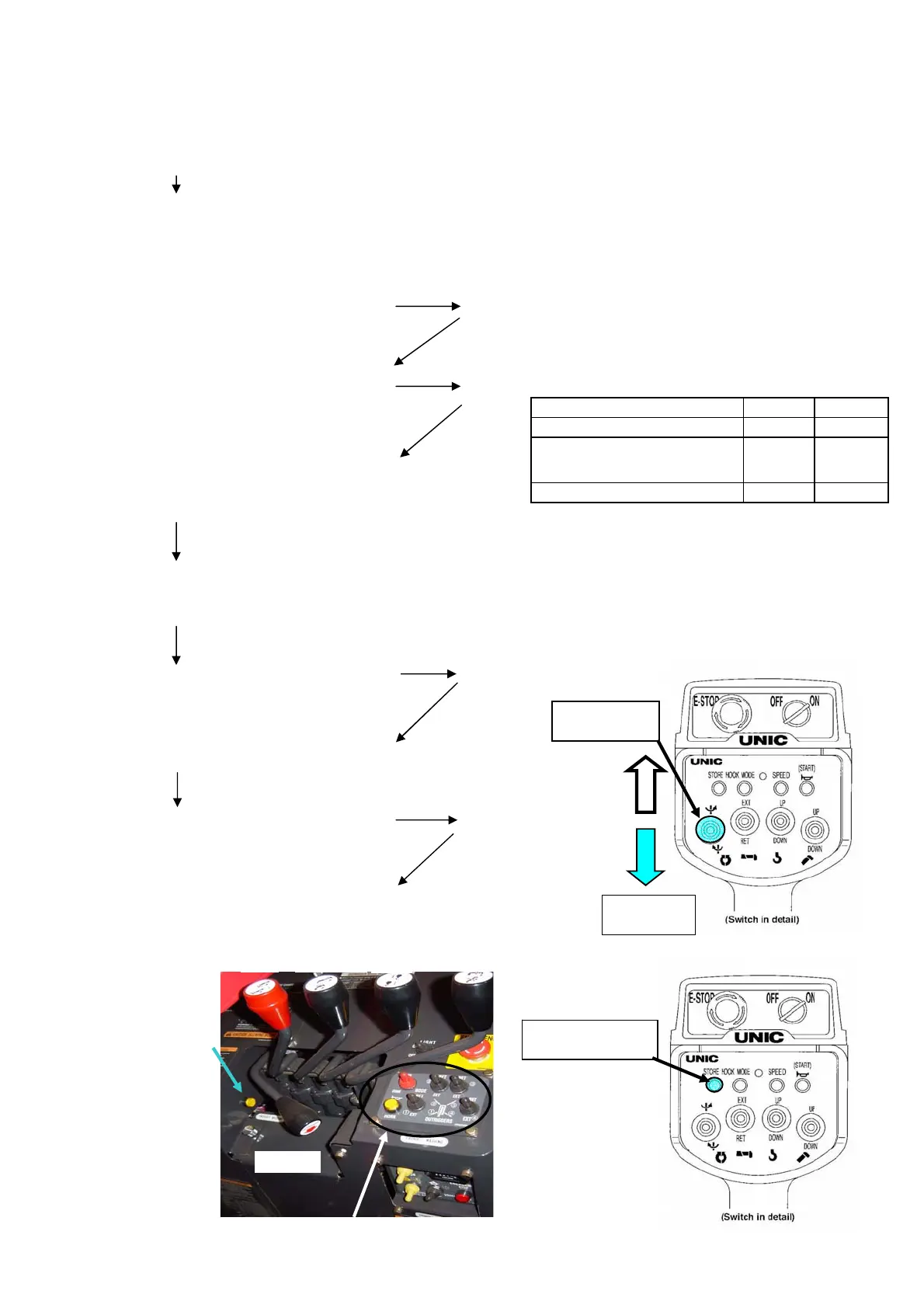
Mode indication
”--” blinks.
3.
Depress “hook storing” switch
within 5 seconds until beep sound is heard.
”Figures” blinks.
Blinking “figures” is for setting type code
Figures Figures
00
4.
02
Afterwards,depress “hook storing”switch When the figure had blinked, it had not fixed it yet.
5.
Afterwards,depress “hook storing”switch
6.
Depress “hook storing”switch
”CC”blinks.
again until beep sound is heard.
7.
Check that each manual control lever stays at its neutral position.
8.
Depress “hook storing” switch
”CF”blinks.
again until beep sound is heard.
9.
Shift manual levers for controlling boom derrick, hook Up/Down,
telescoping, slewing, and outrigger in both directions to their full strokes.
Depress “radio remote control selector
” switch and ”slewing C.W.” switch
simultaneously until beep sound is
heard,
then depress “slewing C.C.W.” switch
within 1 second with“Remote control
selector”switch depressed.
Specification
Normal
Automatic stop leaving
minimam wire rope
01
A left display of "Mode indication" is displayed by
operating "Boom up/down selector" SW, "0".
A right display of "Mode indication" is displayed by operating "Boom
up/down selector" SW, "0"or"1"or"2".
Para-hook
Mode indicator
Hook storing
procedure 3,4,5,6,8
Slewing C.W.
procedure 2
Slewing C.C.W.
procedure 2
Outrigger
Slew Telescope
Hoist
Drrick
The switch of the Outorigger operation is not operated at this time.
Remote control
selector switch
(8-7)
 Loading...