12
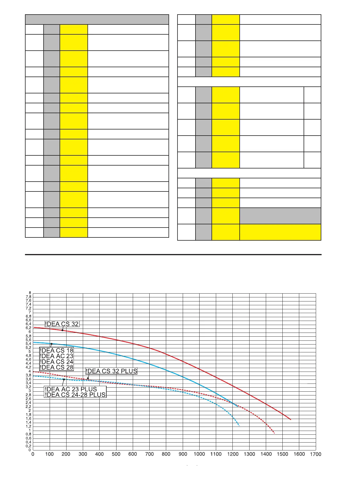
2.3 - DIAGRAM OF FLOW RATE/PRESSURE AVAILABLE FOR
INSTALLATION
KEY
No. C.E. S.E. Description
1 db SS Domestic hot water temper-
ature sensor
2 FLS Flow switch with cold water
lter
3 VG Gas valve
4 Fd E.
ACC/RIL
Ignition/detection electrode
5 Burner
6 Combustion chamber
7 AF TF Flue gas anti-overow ther-
mostat
8 Expansion vessel
9 FR
HT
Heat exchanger
10 HL TL Safety thermostat
11 Hb SR Heating temperature sensor
12 Ht P Pump
13 Lp DK Water deciency pressure
switch
14 Boiler drain valve
15 Filling valve
16 Diverter valve
17 Plate heat exchanger
18 FL
FH
VM Fan
19 AF
AS
PV Flue gas pressure switch
20 Safety valve
21 Automatic by-pass
C Domestic hot water
outlet
G ½
G Gas inlet G ¾
F Cold water inlet G ½
M Heating system ow G ¾
R Heating system re-
turn
G ¾
Rc Filling valve
Sc Boiler drain
Svs Safety valve drain
C.E. = ERROR CODES see
par. 4.6
S.E. = WIRING DIAGRAM
KEY see par. 4.5
Flow rate (l/h)
Avaible Head (m.c.a.) metres of water
 Loading...