11
12 External Equipment Control
The Charger Amplifier provides a variety of I/0 for external device control.
12-1. Horn Speaker (Loudspeaker)
Step 1. Insert the G-Series Pager, turned on, into the Charger Amplifier.
Step 2. Select RCA connector and connect the external equipment.
Step 3. When any message is received, the relay closure is asserted and audio is active.
Step 4. Audio can be terminated by either shutting the G5 off or depressing the Reset button
on the G5.
12-2. Fire Alert Indicator
Step 1. Insert the G-Series Pager, turned on, into the Charger Amplifier.
Step 2. Using the DIN Connector, connect the external equipment to the appropriate signaling
pins.
• Pins 1 and 6 are outputs and are used to control a remote speaker.
• Pins 2 and 3 are normally open dry contacts and close when a page is received.
• Pins 4 and 5 are not utilized on the G4/G5 Amplified Charger, all timing of the dry contacts
is controlled via the Pager Programing Software.
Step 3. Upon receiving a page, the relay and audio output are activated.
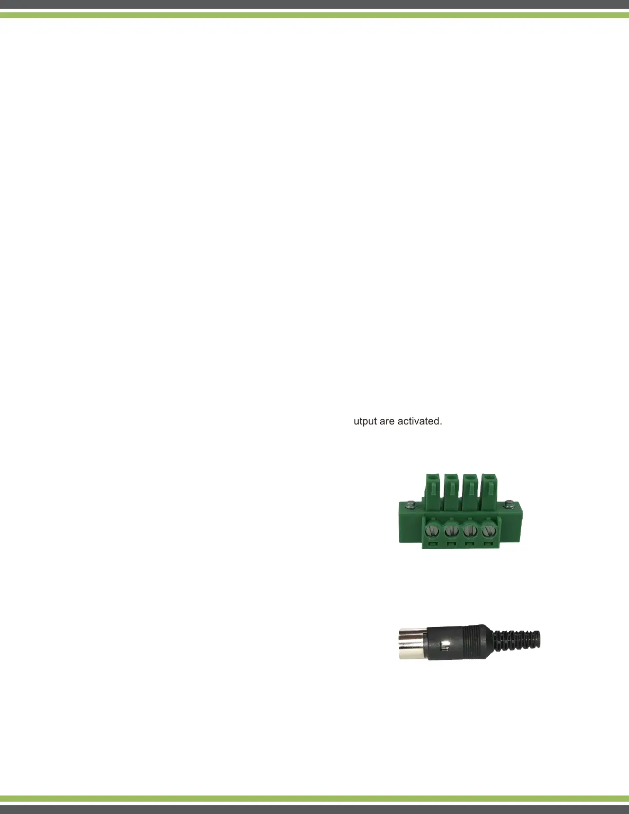
13 Amp Charger Connectors
G-Series Charger Amp Terminal Connector Block
Part Number: 2811923-AMP
G-Series Charger Amp Din Connector
Part Number: CP-1050-ND