Bulletin 30-015.003
Copyright © 2017 Unico Inc. Page 8
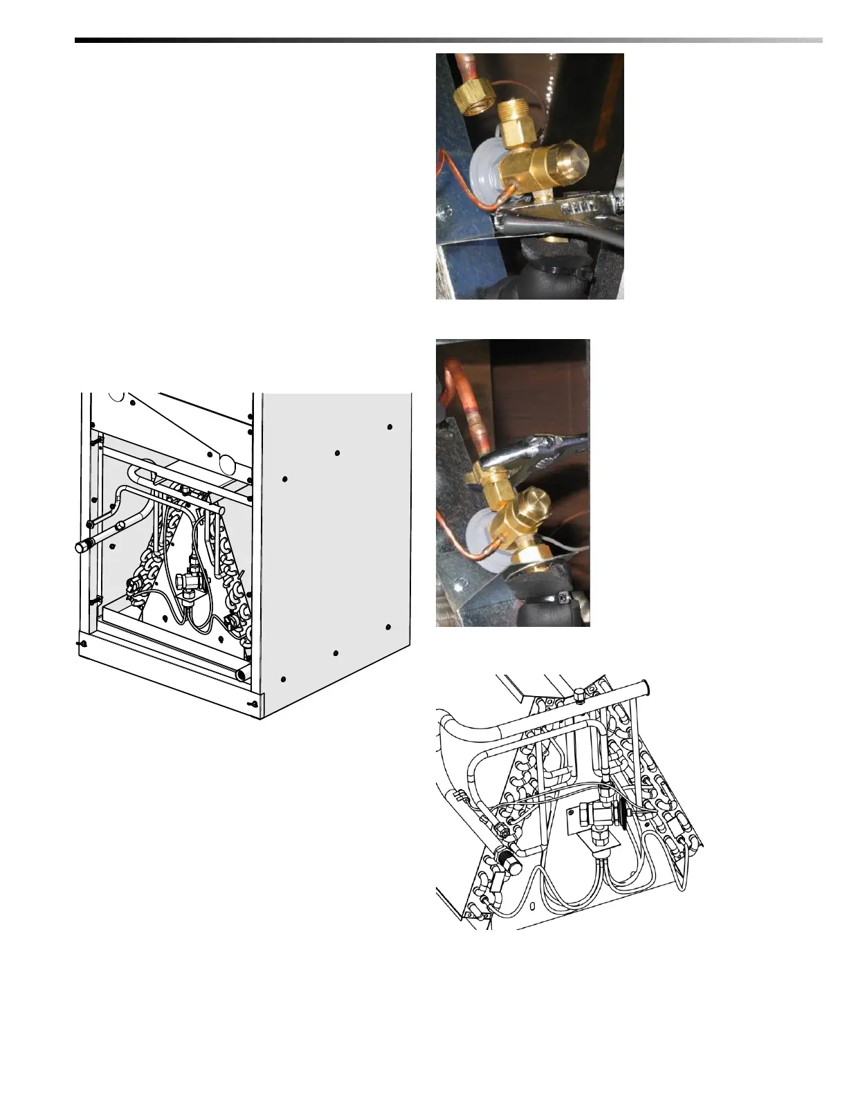
3. Install the white Teflon o-ring in both connections.
Attach and tighten lower connecting nut as shown
in Figure 10.
4. Connect the outlet to the 3/8” (9.5 mm) OD copper
refrigerant fitting. Make sure the flare nut is tight
(Figure 11).
5. After all lines have been connected, pressure check
the connections by charging the system with 150
psig of dry nitrogen and check for leaks at all
connections.
Locate the bulb at the 2, 4, 8, and 10 o’clock position
on a horizontal straight section of the suction line.
Attach the bulb to the tubing with the two pieces of cork
tape that are provided (Figure 12). For satisfactory
expansion valve control, good thermal contact between
the bulb and the suction line is essential.
Figure 9 TXV Placement
Figure 10 Attaching TXV to Distributor
Figure 11 Attaching TXV to Liquid Line
Figure 12 TXV bulb placement

 Loading...