Bulletin 30-015.003
Copyright © 2017 Unico Inc. Page 7
Figure 6 Air Filter Removal
PIPING
All piping must be in accordance with all local codes
and ordinances.
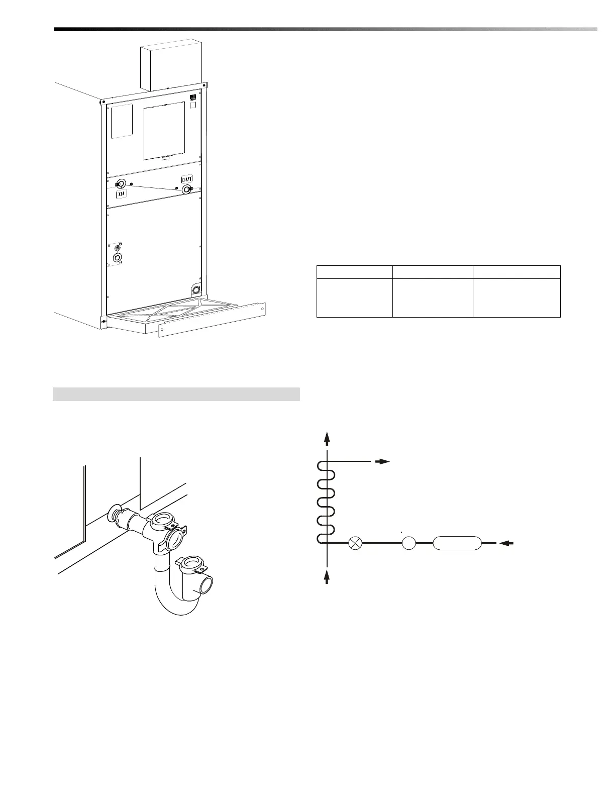
Condensate Lines
Pitch ¼ inch per foot
(2 cm per m)
IL00154b.cvx
Figure 7 Typical Condensate Trap
The primary drain pan condensate connection is a 3/4
inch (19 mm) female pipe thread fitting. Elevate the
unit so the condensate lines are pitched at least ¼ inch
per lineal foot (20 mm per meter). Trap the condensate
line near the unit as shown in Figure 8.
Sent with the Vertical AHU is the Unico Condensate U-
Trap which features a clear trap that is easy to visually
inspect for clogs. The U-Trap is designed for the Unico
System with a 2.5 inch (64mm) deep trap to handle the
higher static pressures. The U-Traps also feature easy to
remove clean-out caps and incorporate tees to
accommodate any piping arrangement (Part No.
A00924-G05).
Refrigerant Connections
CAUTION: WHEN BRAZING, PURGE
WITH NITROGEN GAS TO PREVENT
THE FORMATION OF OXIDES.
The refrigerant lines are copper flare connections. The
sizes are shown in Table 4. Refer to the condensing unit
manufacturer’s instruction for proper line sizing
information based on distance from condenser.
Table 3 Liquid and Suction line size
1/4 Flare
3/8 Flare
3/8 Flare
1/2 Flare
5/8 Flare
3/4 Flare
Install a liquid line filter drier as close to the coil as
possible to protect the evaporator from foreign object
debris. For troubleshooting purposes, especially for
attic installations or when using long line sets, an
optional moisture indicating sight glass should also be
installed between the filter-drier and expansion valve
near the indoor unit (see Fig. 8).
IL00161a.cvx
GLASS
SIGHTTXV
DRIER
AIR
LIQ.
GAS (SUCTION)
EVAPORATOR
COIL
FROM CONDERSER
Figure 8 Refrigeration Schematic
Expansion Valve
The expansion valve is shipped loose inside the spare
parts box which is inside the vertical unit shipping box.
Use the following steps when installing the TXV:
1. Remove plastic caps to external equalizer line and
distributor inlet.
2. Connect valve to distributor (see Figure 9 for
placement)

 Loading...