EasyManuals Logo

unicore UM981 User Manual

Default Icon
27 pages
To Next Page IconTo Next Page
To Previous Page IconTo Previous Page
Page #10 background imageLoading...
Page #10 background image
UC-00-M33 EN R1.0 Introduction 5
Functional Ports
UART × 3
I
2
C
*
× 1
SPI
*
× 1
Slave
CAN
*
× 1
Shared with UART3
1.3 Block Diagram
RF in
SAW
Filter
NebulasIV
GNSS
RF
GNSS
BB
LNA
Interface
PMUInterface
IMU
I
2
C
CLOCK
TCXO
32K
SPI
RESET_N
UART1/2/3
I
2
C
SPIS
PVT/RTK/ERR
EVENT
PPS
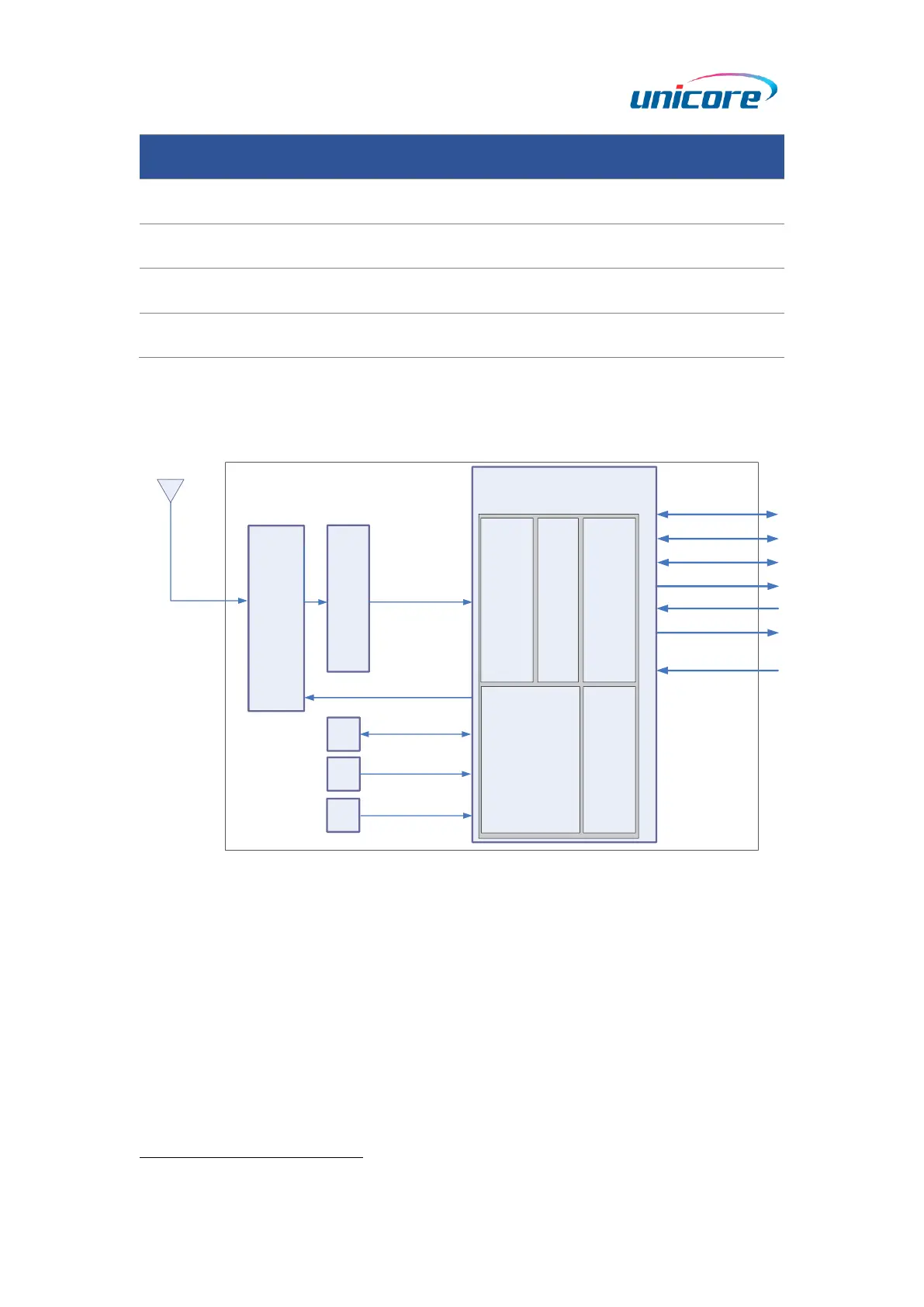
Figure 1-2 UM981 Block Diagram
RF Part
The receiver gets filtered and enhanced GNSS signal from the antenna via a coaxial
cable. The RF part converts the RF input signals into the IF signals, and converts IF
analog signals into digital signals required for NebulasIV
TM
chip (UC9810).
NebulasIV
TM
SoC (UC9810)
NebulasIV (UC9810) is UNICORECOMM’s new generation high precision GNSS SoC with
*
I
2
C, SPI, CAN: reserved interfaces, not supported currently

Questions and Answers:

Question and Answer IconNeed help?

Do you have a question about the unicore UM981 and is the answer not in the manual?

unicore UM981 Specifications

General IconGeneral
Brandunicore
ModelUM981
CategoryControl Unit
LanguageEnglish

Related product manuals