EasyManuals Logo

unicore UM981 User Manual

Default Icon
27 pages
To Next Page IconTo Next Page
To Previous Page IconTo Previous Page
Page #22 background imageLoading...
Page #22 background image
UC-00-M33 EN R1.0 Hardware Design 17
3.4 Grounding and Heat Dissipation
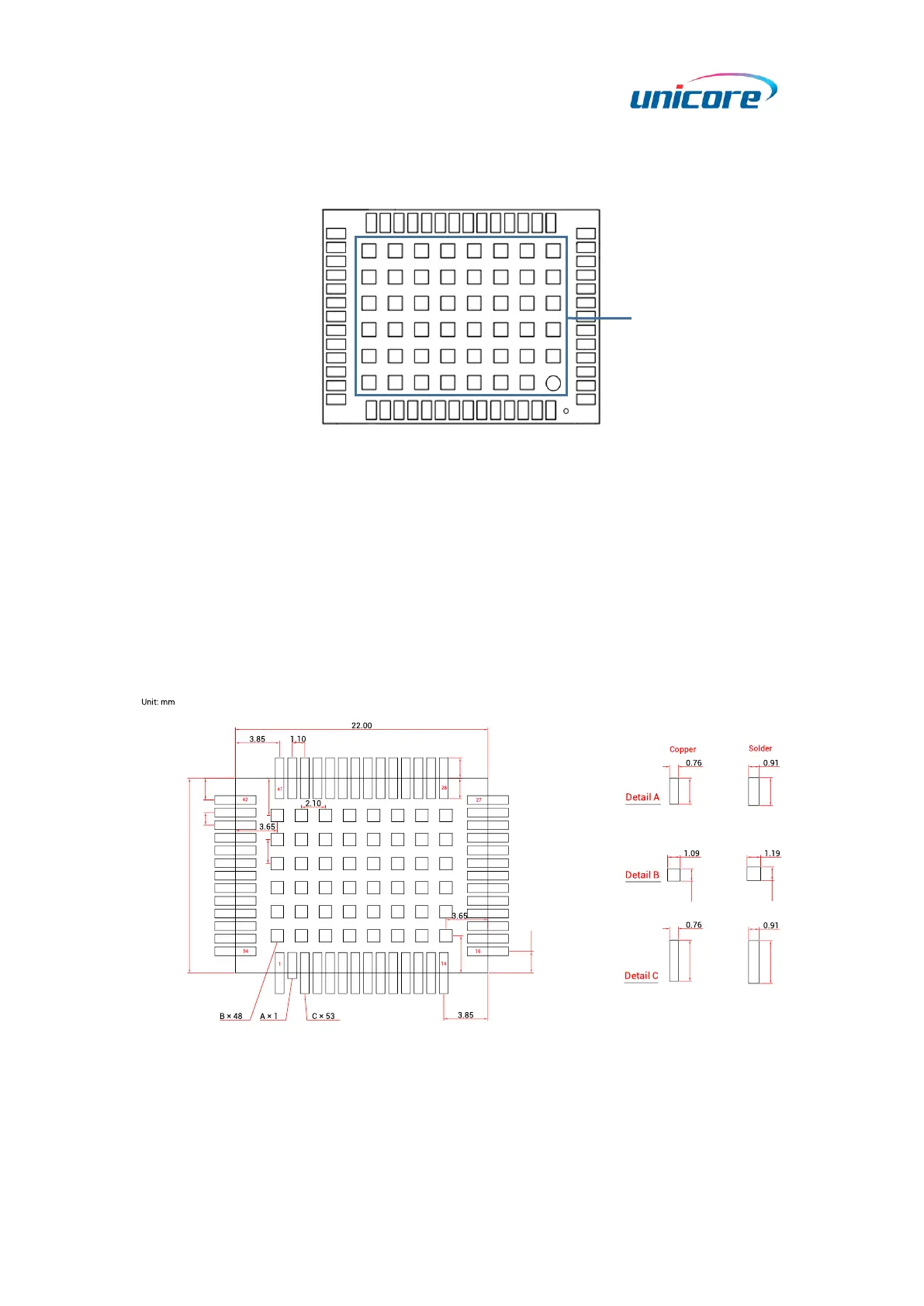
Figure 3-3 Grounding and Heat Dissipation Pad (Bottom View)
The 48 pads in the rectangle area are used for grounding and heat dissipation. In the
PCB design, the pads should be connected to a large-size ground to strengthen the heat
dissipation.
3.5 Recommended PCB Package Design
See the following figure for the recommended PCB package design.
1.79
1.79
2.29
1.09
3.58
3.25
1.90
17.00
1.10
1.90
3.25
.102
2.44
1.19
3.73
Figure 3-4 Recommended PCB Package Design
Notes:
For the convenience of testing, the soldering pads of the pins are designed long,
exceeding the module border much more. For example:
Grounding and
heat dissipation pad

Questions and Answers:

Question and Answer IconNeed help?

Do you have a question about the unicore UM981 and is the answer not in the manual?

unicore UM981 Specifications

General IconGeneral
Brandunicore
ModelUM981
CategoryControl Unit
LanguageEnglish

Related product manuals