Home
UNICORECOMM
GPS
UM982
Page 13 (2.2 Pin Definition)
UNICORECOMM UM982 - 2.2 Pin Definition; 3 Hardware Design; 3.1 Antenna Feed Design
25 pages
Manual
Save Page as PDF
To Next Page
To Next Page
To Previous Page
To Previous Page
Loading...
UM982 User Manual
8
Hardwar
e
UC
-
00
-M31 EN P1.0.0
2.2
Pin Defin
ition
48
47
46
45
44
43
42
41
40
39
38
14
15
16
17
18
19
20
21
22
23
24
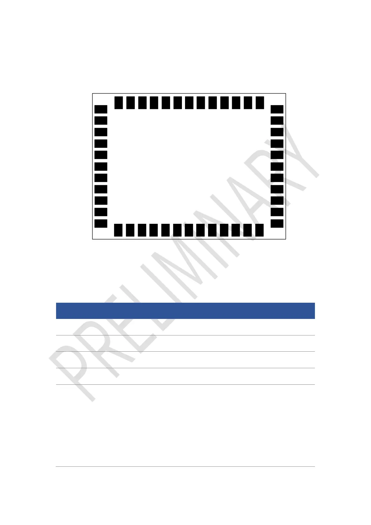
Top View
37
36
35
34
33
32
30
29
28
27
26
25
31
1
2
3
4
5
6
8
9
10
11
12
13
7
SPIS_CSN
V_BCKP
GND
GND
ANT1_
IN
GND
SPIS_MOSI
SPIS_CLK
SPIS_MISO
SPIS_SDRY
RSV
RSV
RSV
GND
ANT2_
IN
GND
GND
RESET
_N
EVENT
RSV
PPS
RSV
RXD3
TXD3
BIF
BIF
RSV
RSV
RSV
GND
ANT2_PWR
GND
ANT1_PWR
GND
RSV
RSV
RSV
ERR_STAT
PVT_STAT
RTK_STAT
RXD1
TXD1
RXD2
TXD2
SCL
SDA
VCC
VCC
Figure2-2 UM982 Pin Definition
T
able 2-2 Pin Description
No.
Pin
I/O
Description
1
GND
—
Ground
2
ANT1_IN
I
GNSS master antenna si
gnal input
3
GND
—
Ground
4
GND
—
Ground
5
V_BCKP
I
When the main pow
er supply VCC is cut off,
V_BCKP supplies pow
er to R
TC a
nd SRAM.
Level require
m
ents: 2.0 V
~ 3.6 V
, and the work
ing
current is about 20 μA at 25
°C
.
Can be floating wh
en the hot start
function is not
used.
12
14
Table of Contents
Main Page
Table of Contents
5
Introduction
6
Key Features
7
Key Specifications
7
Block Diagram
10
Hardware
11
Dimensions
11
Pin Definition
13
Electrical Specifications
16
Absolute Maximum Ratings
16
Operational Conditions
16
IO Threshold
17
Antenna Feature
17
Hardware Design
18
Antenna Feed Design
18
Grounding and Heat Dissipation
19
Power-On and Power-Off
19
Production Requirement
20
Packaging
21
Label Description
21
Product Packaging
21
Related product manuals
UNICORECOMM UM982-EB
26 pages