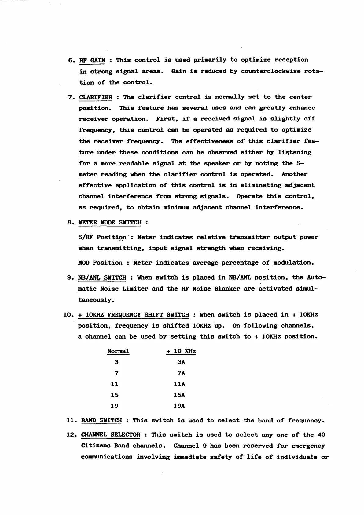
6. RF GAIN : This control is used primarily to optimize réception
in strong signal areas. Gain is reduced by counterclockwise rota
tion of the control.
7. CLARIFIER : The clarifier control is normally set to the center
position. This feature has several uses and can greatly enhance
receiver operation. First, if a received signal is slightly off
frequency, this control can be operated as required to optimize
the receiver frequency. The effectiveness of this clarifier fea—
ture under these conditions can be observed either by liątening
for a more readable signal at the speaker or by noting the S—
meter reading when the clarifier control is operated. Another
effective application of this control is in eliminating adjacent
channel interférence from strong signais. Operate this control,
as required, to obtain minimum adjacent channel interférence.
8. METER MODE SWITCH :
S/RF Position': Meter indicates relative transmit ter output power
when tranamitting, input signal strength when receiving.
MOD Position : Meter indicates average percentage of modulation.
9. NB/ANL SWITCH : When switch is placed in NB/ANL position, the Auto
matic Noise Limiter and the RF Noise Blanker are activated simul-
taneously.
10. + 10KHZ FREQUENCY SHIFT SWITCH : When switch is placed in + lOKHz
position, frequency is shifted lOKHz up. On following channels,
a channel can be used by setting this switch to + lOKHz position.
Normal + 10 KHz
3
ЗА
7
7A
11
11A
15
15A
19
19A
11. BAND SWITCH : This switch is used to select the band of frequency.
12. CHANNEL SELECTOR : This switch is used to select any one of the 40
Citizens Band channels. Channel 9 has been reservéd for emergency
communications involving immédiate safety of life of individuale or




 To Next Page