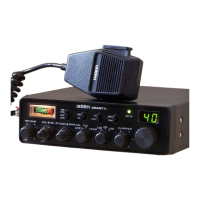
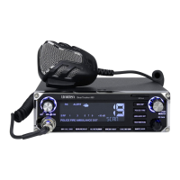
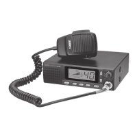
This document is a service manual for the Uniden CB Transceiver, Model JACKSON, specifically the UT-547C/D version. It provides comprehensive information for the installation, operation, maintenance, and alignment of the device.
Function Description
The Uniden JACKSON is a CB (Citizens Band) transceiver, designed for two-way radio communication. It operates across multiple bands (A, B, C, D, E) within the 26-28 MHz frequency range, supporting AM, FM, USB (Upper Sideband), and LSB (Lower Sideband) modulation modes. The transceiver is equipped with a clarifier for fine-tuning the receiver frequency, ensuring clear reception even when the transmitting station is slightly off-frequency. It also includes features like RF Gain, Squelch, Mike Gain, and an ANL/NB (Automatic Noise Limiter/Noise Blanker) switch to enhance audio quality and reduce interference. The device supports both internal and external speaker connections, as well as a public address (PA) function.
Important Technical Specifications
General Specifications:
- Channel and Frequency Range:
- A Band: 26.065 - 26.505 MHz
- B Band: 26.515 - 26.955 MHz
- C Band: 26.965 - 27.405 MHz
- D Band: 27.415 - 27.855 MHz
- E Band: 27.865 - 28.315 MHz
- Crystals: 3
- Microphone: 600 ohms, Dynamic Type
- Speaker: 8 ohms, 3 W
- Antenna Connector: M Type
- Jacks & Connectors: Mic 4P, EXT. SP -3.5Φ, PA. SP -3.5Φ, DC Power -3P
- Controls: Channel Selector, Mode Selector (FM-AM-USB-LSB), Mic Gain, ON/OFF Power Switch & Volume, ON/OFF PA Switch & Squelch, RF Gain, Coarse/Fine, Band Selector (A-B-C-D-E), Noise Blanker/ANL Switch, Roger Beep Switch, S/RF-Mod Switch and +10 KHz / Normal Switch.
- Meter: RF Output Power, Signal Strength and Modulation.
- Illumination: Channel Number Indication (LED), RX, TX Indication (LED), Meter Lamp.
- Size: 7.784"(W) X 2.36"(H) X 11.22"(D)
- Weight: 5 Pounds (2.2 kgs)
- Accessories: DC Power Cable with Built-in Fuse, Microphone and Microphone Hanger.
Measurement Conditions:
- Power Source: 13.8 V (DC)
- Antenna Impedance: 50 ohms
- Test Temperature: 25 °C
- AM Modulation Frequency: 1 kHz
- FM Modulation Frequency: 1 kHz
- SSB Modulation Frequency, Two Tone: 500 Hz & 2.4 kHz
- Mean Signal Input Level: 1.000 uV
- Reference AM Modulation Percentage: 1 kHz 30%
Transmitter Specifications:
- Frequency Tolerance: AM Hz ± 1.500, SSB Hz ± 1.500, FM Hz ± 1.500 (at 25 °C, 5 minutes after switch on).
- Carrier Power: AM V 10.0 (8.0 - 14.0), FM V 10.0 (8.0 - 14.0), Wpep 21.0 (18.0 - 26.0).
- Spurious & Harmonic Emission: AM dB -50 (-40), SSB dB -50 (-40), FM dB -50 (-40).
- Carrier Suppression: SSB dB -55 (-40).
- Unwanted Sideband Suppression (at 500 Hz 4 Wpep 16 dB Single tone): SSB dB -50 (-40).
- Battery Drain at no Modulation: AM mA 3.000 (4.500), SSB mA 500 (1.500), FM mA 3.000 (4.500).
- Battery Drain at Max. Modulation: AM mA 3.000 (4.500), SSB: Max Wpep, Two Tone mA 3.000 (4.500), FM: Max Modulation mA 3.000 (4.500).
- Modulation Frequency Response (1 kHz, 0dB reference): Lower at 450 Hz AM dB -4 (-10), SSB dB -4 (-10), FM dB -4 (-10). Lower at 2.5 kHz AM dB -4 (-10), SSB dB -4 (-10), FM dB -4 (-10).
- Microphone Sensitivity: AM: For 50% Modulation mV 1.0 (2.0), SSB: For 10 Wpep Output mV 1.0 (2.0), FM: For 1 kHz Deviation mV 1.0 (2.0).
- AMC Range: AM: 50 - 100% Modulation dB 50 (40), SSB: dB 50 (40).
Receiver (ANL/NB Switch off) Specifications:
- Max Sensitivity: AM uV 0.5 (2.0), SSB uV 0.25 (1.0), FM uV 0.5 (2.0).
- Sensitivity for 10dB S/N: AM uV 0.5 (2.0), SSB uV 0.25 (1.0), FM uV 0.5 (3.0) (FM: 20dB S/N).
- AGC Figure of Merit, 50 mV for 10dB change in Audio Output: AM dB 80 (70), SSB dB 80 (70).
- Overall Audio Fidelity at 6dB down:
- Upper Frequency AM Hz 2.000 (1.500 - 3.000), SSB Hz 3.000 (2.000 - 4.500), FM Hz 2.500 (1.500 - 3.000).
- Lower Frequency AM Hz 300 (100 - 500), SSB Hz 300 (100 - 500), FM Hz 300 (100 - 500).
- Adjacent Channel Selectivity (10 kHz 1 GEN): AM dB 70 (60).
- Maximum Audio Output Power: AM W 4.0 (3.0), SSB W 4.0 (3.0), FM W 4.0 (3.0).
- Audio Output Power at 10% THD: AM W 2.5 (2.0), SSB W 2.5 (2.0), FM W 2.5 (2.0).
- RF Gain Control Range: AM dB 55 (30 - 70), SSB dB 55 (30 - 70), FM dB 55 (30 - 70).
- S/N Ratio at 1mV Input: AM dB 30 (25), SSB dB 35 (30), FM dB 35 (30).
- Squelch Sensitivity at Threshold: AM uV 0.5 (2.0), SSB uV 0.5 (2.0), FM uV 0.5 (2.0).
- Squelch Sensitivity at Tight: AM uV 1.000 (250 - 4.000), SSB uV 1.000 (250 - 4.000), FM uV 1.000 (250 - 4.000).
- S Meter Sensitivity at "S-9" (No Modulation): AM uV 100 (25 - 400), SSB uV 100 (25 - 400), FM uV 100 (25 - 400).
- Image Rejection Ratio: AM dB 65 (50), SSB dB 65 (50), FM dB 65 (50).
- IF Rejection Ratio: AM dB 85 (70), SSB dB 85 (70), FM dB 85 (70).
- Oscillator Dropout Voltage: AM V 9 (11), SSB V 9 (11), FM V 9 (11).
- Battery Drain at No Signal: AM mA 500 (800), SSB mA 500 (800), FM mA 500 (800).
- Battery Drain at Max. Audio Output: AM mA 1.000 (1.500), SSB mA 1.000 (1.500), FM mA 1.000 (1.500).
- Clarifier Range: AM kHz ± 7.0 (More than ± 5.0), SSB kHz ± 7.0 (More than ± 5.0), FM kHz ± 7.0 (More than ± 5.0).
Public Address:
- Output Power at 10% Distortion: W 2.5 (2).
Note:
- Shall have reverse polarity protection and operable with positive or negative grounding.
- Operating Power Voltage: 13.8V + 15 - 20% DC.
Usage Features
The Uniden JACKSON is designed for ease of operation with several user-friendly controls:
- ON/OFF VOLUME: Turns the transceiver on/off and controls the audio output level.
- SQUELCH: Eliminates undesired background noise when no signal is present. It can be adjusted to a satisfactory level, with the control clockwise to the point where the sound from the speaker is cut off.
- P.A. SWITCH (on SQUELCH) CONTROL: Activates the public address function. The PA function can be used without an external speaker connected.
- MODE SELECTION: This switch selects AM, FM, USB, or LSB modes of operation.
- MIKE GAIN: Controls input sensitivity for optimum amount of modulation in transmit. It's designed to allow users to attain modulation levels up to 100% depending on the microphone provided.
- RF GAIN: Primarily optimizes reception in strong signal areas and reduces unwanted noise.
- CLARIFIER: Fine-tunes the receiver frequency, allowing for clear reception even if the transmitting station is slightly off-frequency.
- METER MODE SWITCH: Selects between S/RF (Signal Strength/RF Output Power) and MOD (Modulation) displays on the meter.
- NB/ANL SWITCH: Activates the Automatic Noise Limiter and RF Noise Blanker to suppress various types of noise.
- +10KHZ FREQUENCY SHIFT SWITCH: Shifts the frequency 10kHz up, useful for operating on specific channels.
- BAND SWITCH: Selects the operating band (A, B, C, D, E).
- CHANNEL SELECTOR: Selects any one of the 40 Citizens Band channels. Channel 9 is reserved for emergency communications.
- ROGER BEEP SWITCH: When activated, the radio automatically transmits an audio signal at the end of your transmission, indicating to the listener that your transmission is over.
Installation Features:
- Location: The transceiver and microphone bracket should be planned for convenient operation and non-interference with the driver or passenger. In automobiles, it's typically mounted to the dash panel.
- Mounting and Connection: The radio is supplied with a universal mounting bracket. The transceiver is held in the bracket by four thumb screws. The mounting surface must be mechanically strong.
- Mounting the bracket: Determine the most convenient location, hold the radio with the mounting bracket in the exact desired position, mark the mounting holes, drill the holes, and then install the radio.
- Antenna Cable: Connect the antenna cable plug to the standard receptacle on the rear panel. Most CB antennas are terminated with a type PL-259 plug.
- DC Power Input: Connect the DC power input wire with the fuse (red) to +12V DC. This wire extends from a plug that connects to the rear panel. In automobile installations, +12V DC is usually obtained from the accessory contact on the ignition switch.
- Ground Wire: Connect the black wire to ground. This is usually the chassis of the car. Any convenient location with good electrical contact may be used (remove paint).
- Microphone Hanger: Mount the microphone hanger on the side of the unit or near the unit using the screws supplied.
Maintenance Features
The manual provides detailed alignment procedures for both the PLL & Carrier Oscillator Portion and the Transmitter Portion, as well as the Receiver Portion. These procedures require specific test equipment and are intended for qualified service personnel.
Alignment Procedures:
- Test Equipment Required: Oscilloscope, DC Power Supply (13.8V), Frequency Counter (0 - 50MHz), DC Voltmeter, AF Signal Generator (1) for 500Hz and 1.000Hz, AF Signal Generator (2) for 2.400Hz, AF VTVM (150mV full scale), RF VTVM (50V full scale), RF Powermeter (10W Max. Thruline type), 50 Ohm Dummy Load, Harmonic Meter, DC Ammeter (150mA full scale), RF SSG, FM Linear Detector, Spectrum Analyzer, Signal Generator, 8 Ohm Resistor.
- Alignment Steps: Detailed step-by-step instructions are provided for adjusting various components (e.g., L12, L13, L14, L15, L16, L24, L23, VR10, VR9, VR7, VR12, VR11, VR4, VR5, VR6, L30, L33, L40, L41, L43, L5, L6, L7, L8, L3, L4) to ensure optimal performance of the transceiver. These adjustments involve connecting specific test equipment to various test points (TP2, TP3, TP4, TP5, TP6, TP7, TP8) and tuning for maximum readings, minimum leakage, or specific voltage/frequency values.
- Schematic Diagrams/Wiring Diagram/PC Boards: The manual includes detailed schematic diagrams (E12-2108 and E12-2108 REVISED), a main PCB parts assembly top view (E22-4674), and a wiring diagram (E32-2212) to aid in troubleshooting and repair.
- Bill of Material: A comprehensive list of components (25 P.S) is provided, including codes, designations, and quantities, which is essential for parts replacement and repair.
The manual emphasizes the importance of proper grounding for the radio, whether negative or positive, and notes that the device is designed with reverse polarity protection. It also provides a table of frequencies for each channel across the five bands, which is crucial for understanding the device's operational range.

 Need help?
 General


 To Next Page