PART I: SPECIFICATIONS
11
Checking the proper gas train size
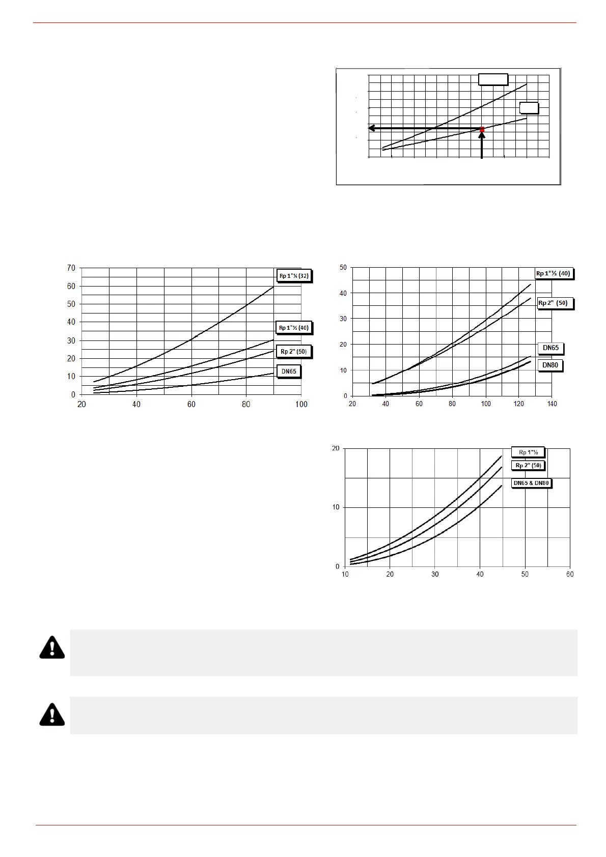
Pressure in the Network / gas flow rate curves
Natural Gas burners
To check the proper gas train size, it is necessary to the available
gas pressure value upstream the burner’s gas valve. Then subtract
the backpressure. The result is called pgas. Draw a vertical line
matching the furnace input value (600kW, in the example), quoted
on the x-axis, as far as intercepitng the network pressure curve,
according to the installed gas train (DN65, in the example). From the
interception point, draw an horizontal line as far as matching, on the
y-axis, the value of pressure necessary to get the requested furnace
input. This value must be lower or equal to the pgas value, calcula-
ted before.
GAS PRESSURE IN
THE NETWORK mbar
C85A M-..
Stm
3
/h
C120A M-..
Stm
3
/h
GAS PRESSURE IN
THE NETWORK mbar
C120A L-..
Stm
3
/h
ATTENTION: the gas rate value is quoted on the x-axis, the related network pressure is quoted on the y-axis
(pressure value in the combustion chamber is not included). To know the minimum pressure at the gas train inlet,
necessary to get the requested gas rate, add the pressure value in the combustion chamber to the value read on
the y-axis.
The values in the diagrams refer to natural gas with a calorific value of 8125 kcal/Stm
3
(15°C, 1013 mbar) and a density of
0.714 kg/Stm
3
.
0
5
10
15
20
25
100 200 300 400 500 600 700 800 900
Potenza / Output (kW)
Minima pressione gas in
rete / Minimum inlet gas
pressure (mbar)
Rp 2" (50)
DN65
Power kW
minimum gas pressure in
the network mbar
DN65


 To Next Page