PART II: INSTALLATION
24
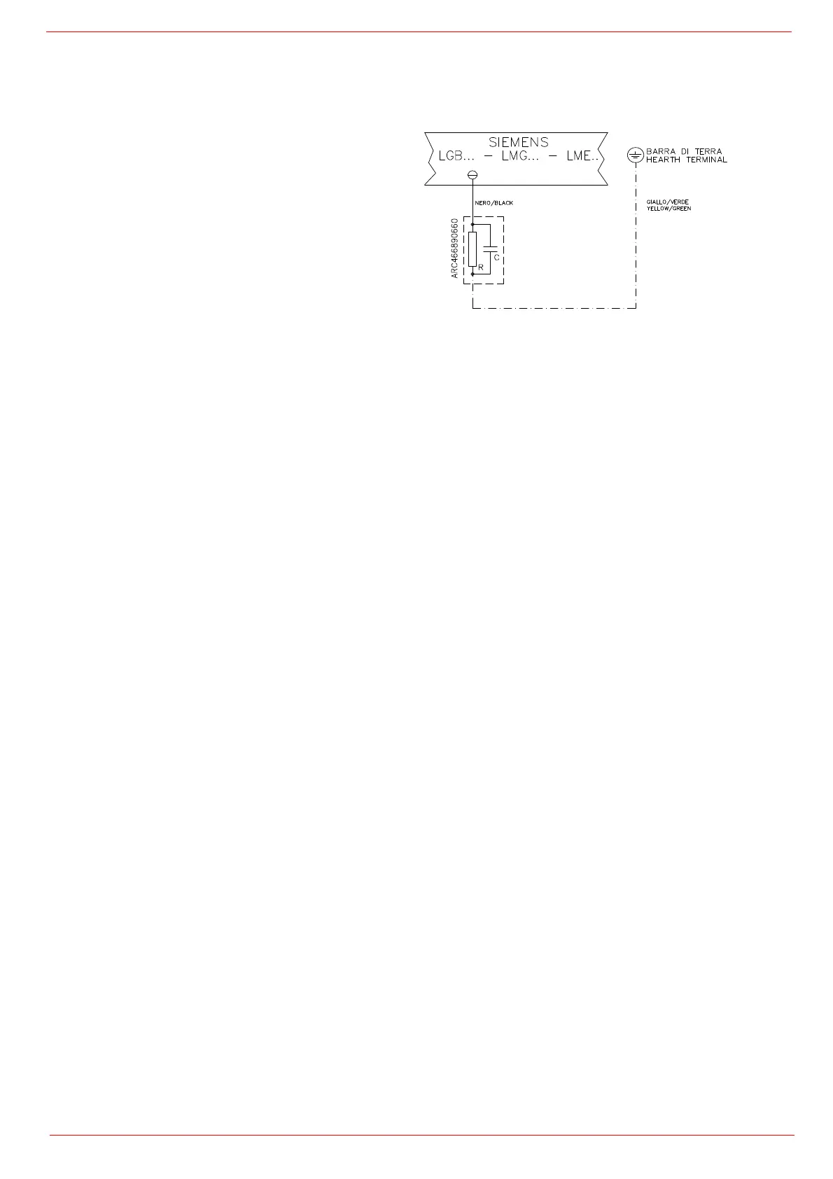
Note on elecrtical supply
If the power supply to the burner is 230V three-phase or 230V phase-phase (without a neutral), with the Siemens control box, between
the terminal 2 (terminal X3-04-4 in case of LMV2x, LMV3x, LMV5x, LME7x) on the board and the earth terminal, an RC Siemens
RC466890660 filter must be inserted.
For LMV5 control box, please refer to the clabeling recommendations avaible on the Siemens CD attached to the burner
Configuration with separate electrical panel (optional)
The length of the electrical cables must comply with the provisions in the technical sheets of the equipment or the advice the company
gives at the time of the offer/contract.
Provide sufficient protections for cables and connectors, taking into consideration positioning spaces and the panel-burner tracing sur-
faces. Always consult beforehand the electrical drawings supplied in relationship to the topography of the feeding systems.
Key
C - Capacitor (22nF/250V)
LME / LMV - Siemens control box
R - Resistor (1MΩ)
M - Terminal 2 (LGB,LMC,LME), terminal X3-04-4 ( LMV2x,
LMV3x, LMV5, LME7x)
RC466890660 - RC Siemens filter
 Loading...