7
1.4 Wireway and electrical conduit
The following cables are recommended for separate wiring;
Complete separate from all other cables:
• Cable for "VSD to Fan motor" Line voltage, see also "1. Frequency inverter / Variable Speed Drive (VSD)"
• Cable for ignition high voltage, see also "2. Ignition"
• Cable for the Flame sensors
Together in cable duct 1 for Low voltage, e.g.:
• Cable for CAN-Bus
• Cable for VSD speed sensor, LMV5 X70
• Cable for VSD Release & Set point , LMV5 X73
• Cables for the Load controller: Temperature or Pressure sensor, set point, load output at the LMV5 X60, X61, X62, X63
Together in cable duct 2 for Line voltage, e.g.:
• Cable for Ignition transformer
• Cables for other Line voltage signals, e.g. Gas pressure switches, Air pressure switches, ….
• Cable for Gas valves SKP/VGD
Example of wiring, see next paragraph Wireway and electrical conduit
NOTE: KEEP SEPARATE SIGNALS CABLES, OUTPUT CABLES, PHOTOCELL CABLE AS SHOWN IN THE BELOW PICTURE
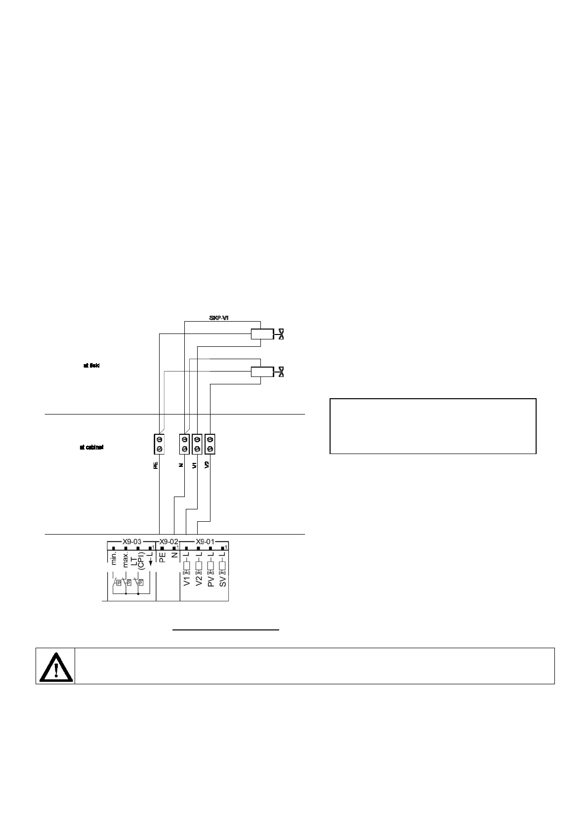
The cables from the LMV5 to the SKP/VGD -Gas
vales shall be connected at the LMV5 side with X9-01:
L-Valve1, L-Valve2 and with X9-02, N, PE) and
connected at the SKP side separate to each SKP.