Do you have a question about the Unigas LG140 Series and is the answer not in the manual?
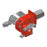
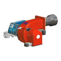
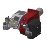
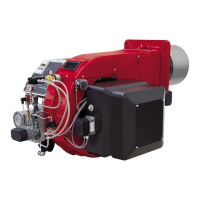
This document describes the UNIGAS Idea Series gas burners, specifically the LG/NG140, LG/NG200, LGX/NGX120, and LGX/NGX200 models, which are progressive and fully-modulating. It serves as a comprehensive manual for installation, use, and maintenance.
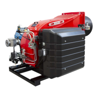
The UNIGAS Idea Series burners are designed for efficient and safe operation in heating systems. They feature a removable ABS plastic cover, which is heat and crash-proof. The design incorporates a shifting flange for efficient tightness and space-saving. All mechanical components are mounted on a removable plate, simplifying routine maintenance. The combustion head position can be easily adjusted using an indexed screw, and a unique air intake design helps reduce noise levels.
The gas supply passes through a valve group equipped with a filter and stabilizer, which ensures the pressure remains within specified limits. For double-stage, progressive, and fully-modulating burners, an electric servocontrol (5) proportionally moves the air damper using an adjustable cam. This cam's variable shape optimizes gas flue values for efficient combustion. The combustion head's positioning determines the burner output. Fuel and combustion air are routed separately until they reach the flame generation zone (combustion chamber).
The burners are available in various models, identified by type and specific configurations. Key specifications include:
NG140 Series (Natural Gas):
LG140 Series (L.P.G.):
NG200 Series (Natural Gas):
LG200 Series (L.P.G.):
NGX120 Series (Low NOx, Natural Gas):
LGX120 Series (Low NOx, L.P.G.):
NGX200 Series (Low NOx, Natural Gas):
LGX200 Series (Low NOx, L.P.G.):
All gas flow rates are referred to 1013 mbar absolute pressure and 15 °C temperature. Natural gas (G20) has a net calorific value of 34.02 MJ/Stm³, and L.P.G. has 93.5 MJ/Stm³. Maximum gas pressure is 360 mbar (with Dungs MBDLE/MBC valves).
Installation: Installation must be performed by qualified personnel in compliance with regulations. The burner must be firmly secured to the appliance. Before commissioning, the fuel supply system, flow rate, firing system, supply pressure, and safety devices must be inspected. The burner should be installed in a suitable, well-ventilated room.
Electrical Connection: The unit must be efficiently earthed. An omnipolar switch is required for mains connection. No adaptors or extension cables are permitted. For 230V phase-phase power supply without a neutral wire, an RC Siemens RC466890660 filter must be inserted between terminal 2 on the board and the earth terminal of the Siemens LME control box.
Operation: The burner is designed to operate only when correctly connected to a heat generator. It is crucial to ensure the main switch is ON and manual shutoff valves are open before starting. In case of a burner shut-down, the control box can be reset using the RESET pushbutton. If a second shut-down occurs, technical service should be contacted.
Adjusting Air and Gas Flow Rates: Adjustments involve unscrewing fixing screws and removing the burner cover. The start-up heat output should not exceed 120 kW (single-stage burners) or 1/3 of nominal output (progressive/fully modulating burners). Combustion air excess must be adjusted according to recommended CO2 and O2 percentages (Natural gas: 9-10% CO2, 3-4.8% O2; LPG: 11-12% CO2, 2.8-4.3% O2). The air and gas flow rates are adjusted at maximum output ("high flame") first, using the air damper and adjusting cam. The low flame output is set by acting on the low flame microswitch of the actuator.
Gas Pressure Switches: The air pressure switch locks the control box if the air pressure is not as requested. Gas pressure switches ensure the burner operates within the specified pressure range. Calibration involves turning the adjusting ring nut VR clockwise until lockout, then setting it to a value reduced by 15%. For maximum gas pressure switch, the value is set to the network pressure increased by 30%.
Routine maintenance should be performed at least once a year, or every 6 months for continuous operation. All operations must be carried out with the mains disconnected and fuel manual cutoff valves closed.
Routine Maintenance includes:
Removing the Filter (MULTIBLOC DUNGS MB-DLE 405..412 and 415-420 B01 1” 1/2 - 2”): The filter should be checked at least once a year and replaced if the pressure difference across it exceeds 10 mbar or is twice as high as the last check. The filter can be changed without removing the fitting by interrupting the gas supply, removing screws, replacing the filter, and re-inserting the cover.
Disassembling the Burner Plate: To service the burner fan, the component plate is removed by unscrewing securing screws and removing cable holders. The rod is freed, and the connector is disconnected to facilitate maintenance. When reassembling, ensure the pin for the air damper enters its housing correctly.
Removing the Combustion Head: To remove the combustion head, the burner cover and VT fixing screws are unscrewed. The ignition cable is disconnected, and fixing nuts are unscrewed to shift the combustion head. Electrodes are adjusted or replaced as needed. The combustion head is cleaned using a vacuum cleaner and a metallic brush to scrape off scale. During reassembly, screws V1, V2, V3, S1, and S2 must be tightened.