USSI Microlok II Functional description
Page 12 of 27 July 2005 UM-6800A Rev1.3
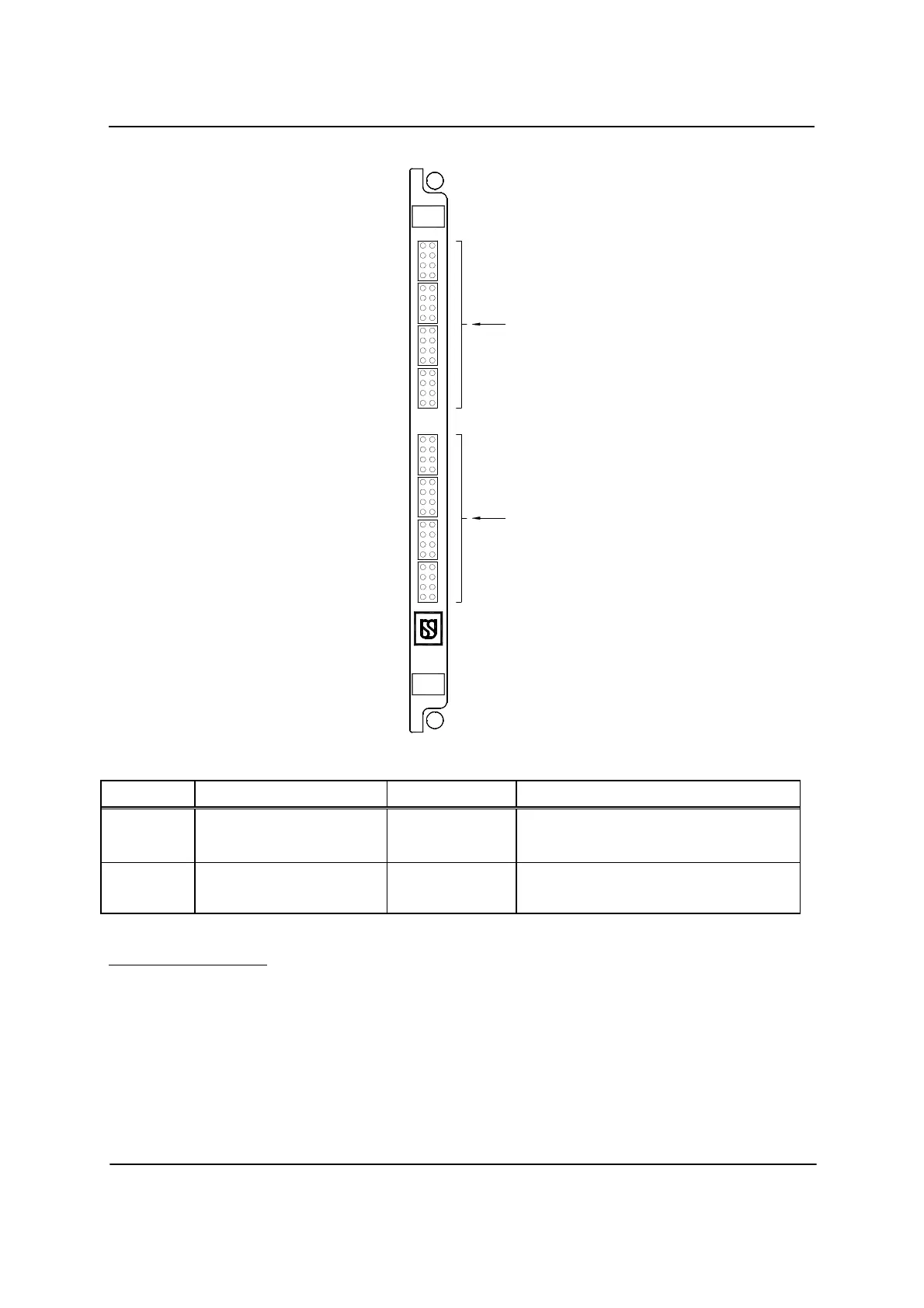
Figure – 4
Fig. 4 Ref Label Device Purpose
1
INPUTS 1-32
Green LEDs Monitors states of non-vital inputs 1-32.
When LED is lit, respective input is on.
2
OUTPUTS (SWITCHED TO
N12) 1-32
Yellow LEDs Monitors states of non-vital outputs 1-32.
When LED is lit, respective output is on.
Vital Output Board
Outputs are controlled by “high side” software-controlled switches. Loads
should be connected from outputs to battery negative. The high side switch is
used to connect battery (+) to the output. Each output is protected with a
polyswitch, which acts like an auto circuit breaker. When the over current
trip point is reached (approximately 0.75A), the polyswitch switches to a high
impedance state. The switch resets to its low impedance state when the
additional load or short is removed. A short to battery (-) will trip the
NV.IN32
1
1
2
3
4
7
8
5
6
11
12
10
9
16
14
15
13
INPUTS
16
15
13
14
12
10
11
9
7
8
6
TO N12
3
4
5
1
2
SWITCHED
OUTPUTS
32
31
29
30
28
26
27
25
23
24
22
19
20
21
17
18
32
31
30
29
28
27
26
25
24
23
22
21
20
19
18
17
.OUT32
2
 Loading...