USSI Microlok II Functional description
UM-6800A Rev1.3 July 2005 Page 13 of 27
polyswitch and cause the VCOR relay to drop, but will not cause any
damage. A short to battery (+) will not cause any damage, but since this
condition is equivalent to a false output, the Microlok II CPU will cause the
VCOR relay to drop.
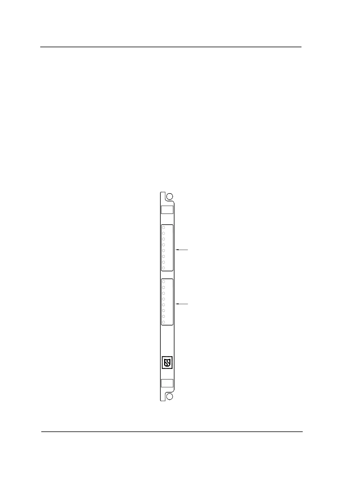
• Each Vital Output PCB is having 16 outputs.
• Each output is assigned to the final relay which is driving the outdoor
signalling gears such as HR, DR in case of signal & WNR, WRR in case of
points.
• Since the output boards are driving outdoor gears, they are continuously
monitored by the CPU and any abnormal voltage present in the output will
lead to system reset / shutdown to ensure safety
Figure – 5
OUT16
OUT 16
OUT 15
OUT 14
OUT 11
OUT 13
OUT 12
OUT 10
OUT 3
OUT 7
OUT 9
OUT 8
OUT 5
OUT 6
OUT 4
OUT 1
OUT 2
2
1
 Loading...