USSI Microlok II Functional description
UM-6800A Rev1.3 July 2005 Page 7 of 27
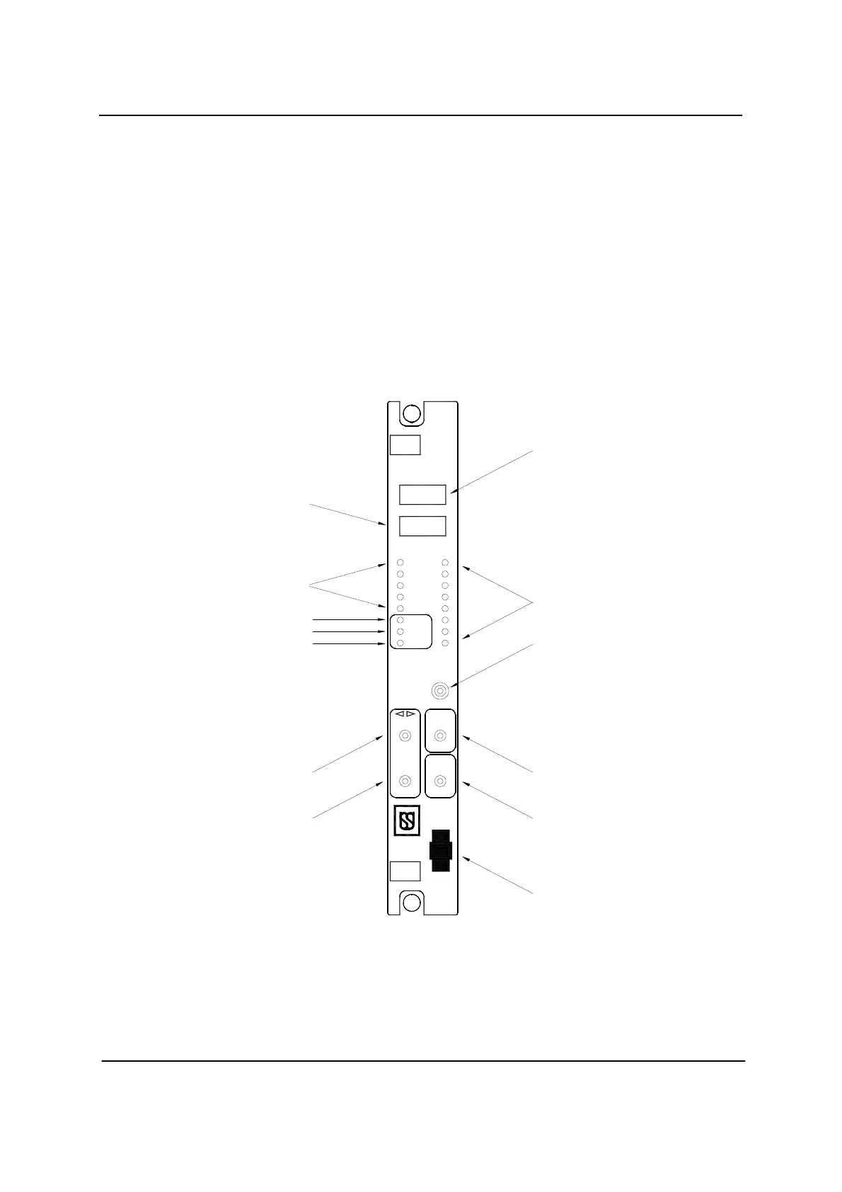
programming and to select the required programming voltage. The CPU board
contains the central controlling logic and diagnostic monitoring for the
Microlok II system, and provides five serial data ports. The CPU connector
housing has an internal EEPROM that is used to store site-specific
configuration data. Even if the CPU board is replaced, the configuration data
remains intact within the CPU connector’s EEPROM.
• Ports 1 and 2 support an RS-485 hardware interface
• Port 3 supports an RS-423 & RS 232 interface
• Port 4 & 5 supports an RS-232 interface
Figure – 2
ADJUST
UP
DOWN
REJECT
ACTION
ACCEPT
RESET
DOWN
UP
L R
M
E
N
68332
CPU
ON-LINE
VPP ON
RESET
E
D
C
B
A
2
4
5
3
1
7
8
6
1 2
3
4
CAB D
DTE
RS-232
13
12
11
8
4
1
10
9
7
6
5
3
2
U
 Loading...