Page 21
POWERING TECHNOLOGY
Manual No. aspiro2u-3
aspiro2u_m23-man-rev3-0516.indd
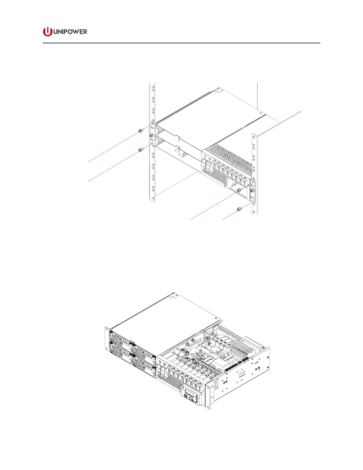
4. Then fasten the subrack, either with adjustable or xed brackets, to the cabinet with four
M6 x 12mm (2 on each side of the subrack). Tighten the screws to 6Nm, Figure 4-3.
Figure 4-3 System Bracket Fixing
4.4 Cable Entry
If the top distribution cover is installed, it should be removed for connecting AC, DC, alarm,
grounding, temperature and symmetry measurement cables.
Push the top cover backwards and then lift it to remove.
Figure 4-4 System With Cover Removed
 Loading...