Page 25
POWERING TECHNOLOGY
Manual No. aspiro2u-3
aspiro2u_m23-man-rev3-0516.indd
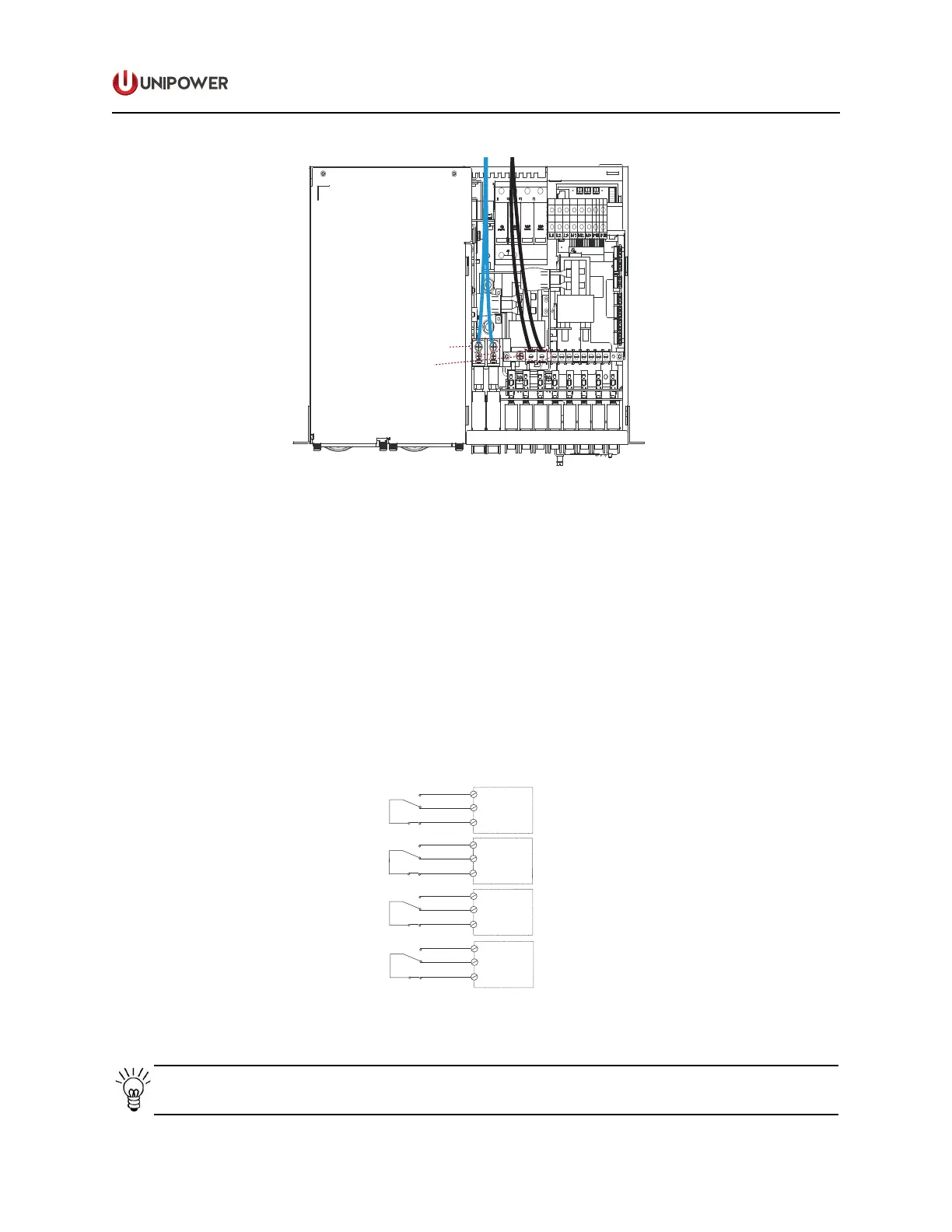
Battery -48 V
Battery 0V
Figure 4-9 Battery Connection
4.9 Alarm and Signal Connections
For remote supervision of the alarms, there are a maximum 4 potential free alarm contacts
available. Each alarm contact represents dierent alarm condition, dependent on system
conguration.
The alarm connections are located on the top right side of the subrack on the Alarm Interface.
Use suitably sized alarm cables: Max. 14AWG/1.5mm².
The Connection of all alarms are shown in Figure 4-10.
1
2
3
X
C5
X
C5
1
2
3
X
C6
X
C6
4
5
6
4
5
6
Alarm
Alarm
Alarm
Alarm
NO
NO
NO
NC
NC
NC
NC
C
C
C
C
Figure 4-10 Alarm Connections
NOTE Alarm contacts are shown in alarm position.
 Loading...