Do you have a question about the Unitech UT-101 and is the answer not in the manual?
Guidelines for electrical safety and precautions during installation and operation.
Details on power supply voltage compatibility and required wiring practices.
Information on connecting the controller to AC or DC power mains.
Procedures for disposing of instruments according to regulations.
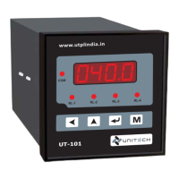
Overview of the UT-101 indicator and controller functionalities.
Instructions and specifications for mounting the instrument and its physical dimensions.
Details on supported input types, accuracy, and range limits.
Specifications for output signals, communication protocols, and power supply.
Detailed wiring diagrams for specific UT-101 model sizes.
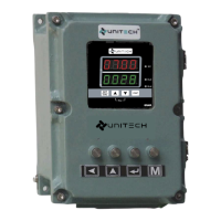
Description of the front panel interface, LEDs, and keys for operation.
Visual guide illustrating the navigation between different programming modes.
Details on parameters and values for configuring the device.
Parameters and their ranges for the setup mode.
Steps for calibrating the instrument for different input types and outputs.
Procedure for changing the device password and related precautions.
Table of common error messages and their corresponding solutions.
Basic settings for RS-485 Modbus communication protocol.
List of parameters and their absolute addresses for Modbus RTU.
Diagram illustrating the Modbus RS-485 communication system setup.
| Brand | Unitech |
|---|---|
| Model | UT-101 |
| Category | Controller |
| Language | English |