5. COMMUNICATION [MODBUS RTU] PROTOCOL
5.1 Introduction
The unit can be connected in MODBUS/RTU communication data link protocol to messaging
structure, widely used to establish master - slave communications between devices. Each
device must have unique No. node address. Before starting any communication, choose a
baud rate compatible to the host device. A Modbus data sent from a master to slave tells the
selected slave what to do and what information to send back. The MODBUS/RTU protocol
works with RS232, RS485 and RS422 standards
5.2 MODBUS Configuration Basic settings
The Basic settings for RS-485 Modbus protocol are as follows :
Band rate
Start bit
Data bit
Stop bit
Parity
9600
1
8
1
none
5.3 Register addresses for MODBUS / RTU Protocol
The addressees for RS-485 Modbus protocol are as follows :
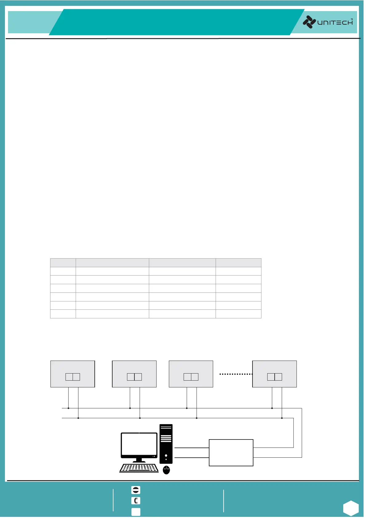
5.4 MODBUS system schematic.
DATA+
READ ONLY
SR. NO.
1 PROCESS VALUE [PV]
PARAMETER ABSOLUTE ADDRESS ACCESS TYPE
40001
READ / WRITE
3 SET POINT-1 [SP1] 40003
READ ONLY
2 DECIMAL POINT 40002
READ / WRITE
4 SET POINT-2 [SP2] 40004
READ ONLY
5 RELAY-1 STATUS 40005
READ ONLY
6 RELAY-2 STATUS 40006
The system schematic for RS-485 Modbus protocol are as follows :
DATA-
Ethernet
RS-232
or
RS-485
CONVERTER
D- D+
1
2
UT-101 Device-1
D- D+
1
2
D- D+
1
2
D- D+
1
2
RS-485 BUS
ADD:1 ADD:2 ADD:3 ADD:N
RS-485 BUS
Upto 128
devices
UT-101 Device-2 UT-101 Device-3
UT-101 Device-128
2 core 1 sq/mm shielded cable
www.utplindia.in
@
www
sales@utplindia.in
+91 7046223333 , 9427301436
All content are subject to change without notice
due to continuous improvements.
Doc. Ref. 1410/R04/0819
UNITECH TECHNOCRATS PVT LTD
FACTORY:- 78/1/Z/3-Makarpura G I D C.. . .,
N/R Vadasar Bridge. /p-Gayatri empleOT
VADODARA - 390010 INDIA. Gujarat,
13
UT-101
UNIVERSAL PROCESS INDICATOR CONTROLLER&
COMPUTER- SCADA