Install the module in an upright position.
To ensure good ventilation, leave at least 50mm between the
device and all other objects above or below it.
Install at a maximum distance from high-voltage cables and
power equipment.
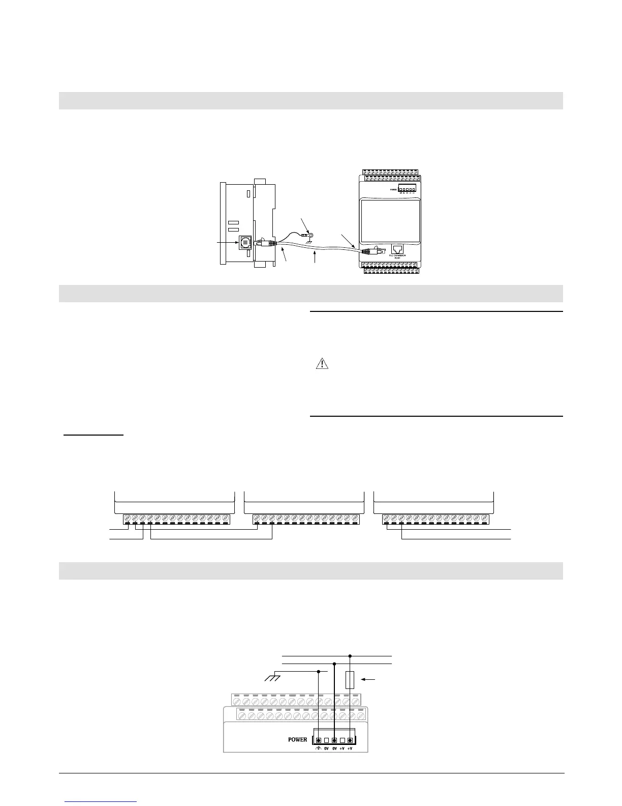
Connecting the Module to the PLC
Use the communication cable to connect the module’s PLC expansion port to the PLC.
Take care to connect the correct cable. The connectors of this cable are housed in yellow insulation. Note that one end is
marked To PLC and the other To Adapter; insert accordingly.
The module is supplied with a 1-meter cable, part number EXL-CAB100. Other cable lengths are also available.
Use only an original Unitronics cable and do not make any changes to it.
PLC Controller
Earth
Ground
I/O
Expansion
Port
To PLC
EXL
–
CAB
100
TO PLC
EXL–CAB100
TO
ADAPTER
To Adapter
Use crimp terminals for wiring and use 26-12 AWG wire
(0.13mm
2
–3.31mm
2
).
Strip the wire to a length of 7±0.5mm (0.250–0.300”).
Do not route input cables together with output cables
through the same multi-core cable or wire.
Use wire that is correctly sized for the load. Allow for
voltage drop and noise interference with extended input
lines.
Note: Connect the adapter 0V and the I/O 0V to the same
line
Install an external circuit breaker. Guard against
short-circuiting in external wiring.
Do not connect unused pins. Ignoring this directive
may damage the device.
To avoid damaging wires, do not exceed a maximum
torque of 0.5 Nm (5 kgf·cm).
Do not use tin, solder, or any substance on stripped
wire that might cause the wire strand to break.
Daisy Chaining
To facilitate wiring, you can wire the following pins in series (daisy chain). Use both pins provided for this purpose.
Input connector pin: n/p. Output connector pins: +V, 0V. Power connector pins: +V, 0V.
Ensure that the total current drain on any single line does not exceed 10A. If a specific pin requires more than 10A, connect it
with a separate wire. The following diagram demonstrates the wiring options:
+V
0V
+V
0V
+V +V 0V 0V
+V +V 0V 0V
+V +V 0V 0V
Individual ConnectionDaisy-chained Connection
Always connect the functional earth pin to the earth ground. Use a dedicated wire for this purpose; it must not exceed 1
meter.
A non-isolated power supply can be used provided that the 0V signal is connected to the earth ground.
Do not connect the neutral or line signal of the 110/220VAC to the device’s 0V pin.
In the event of voltage fluctuations or non-conformity to voltage power supply specifications, connect the device to a
regulated power supply.
0V
+V
Circuit
Protection
Device
 Loading...