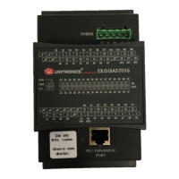
The following diagram shows the input connectors with pin numbers and corresponding input numbers
14131211109
8
765
4
3
2
1
n/p
RG
n/p3938373635343332
RG
15 16 17 18 19 20 21 22 23 24 25 26 27 28
AI1
AI0AI2
46454443424140 47
Wiring Digital Inputs
Inputs may be wired as either pnp (positive logic) or npn (negative logic).
Input 36 can function as a high-speed counter, frequency measurer, or general purpose digital input (set in software).
Input 37 can function either as a counter reset input or general purpose digital input (set in software).
For correct operation of the digital inputs, connect the n/p pin according to the following figures.
For information on connecting RG pins, refer to Connecting RG Pins.
pnp (positive logic) inputs 32-39
pnp (positive logic) inputs 40-47
14131211109
8
765
4
3
2
1
15 16 17 18 19 20 21 22 23 24 25 26 27 28
0V
+V
RG
*
‡
*
HSC Input
‡
Counter Reset
n/p
RG
I32
I33
I34
I35
I36
I37
I38
I39
14131211109
8
765
4
3
2
1
15 16 17 18 19 20 21 22 23 24 25 26 27 28
0V
+V
RG
n/p
RG
*
HSC Input
‡
Counter Reset
I40
I41
I42
I43
I44
I45
I46
I47
npn (negative logic) inputs 32-39
npn (negative logic) inputs 40-47
14131211109
8
765
4
3
2
1
15 16 17 18 19 20 21 22 23 24 25 26 27 28
0V
+V
RG
n/p
RG
*
HSC Input
‡
Counter Reset
*
‡
I32
I33
I34
I35
I36
I37
I38
I39
*
HSC Input
14131211109
8
765
4
3
2
1
15 16 17 18 19 20 21 22 23 24 25 26 27 28
0V
+V
RG
n/p
RG
‡
Counter Reset
I40
I41
I42
I43
I44
I45
I46
I47
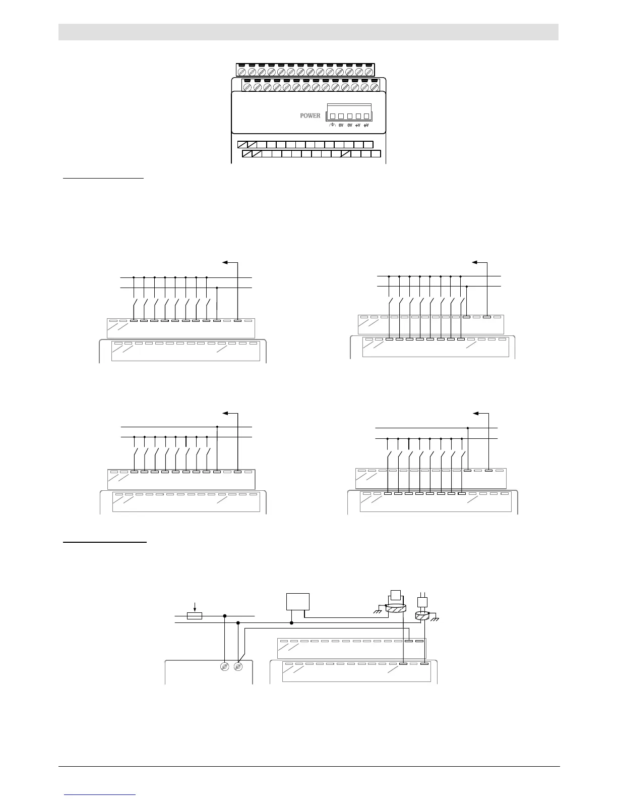
Wiring Analog Inputs
The following diagram shows the 2-wire and 4-wire current connection.
Use shielded twisted pair cable.
Connect shields to the earth ground at the signal’s source.
14131211109
8
765
4
3
2
1
15 16 17 18 19 20 21 22 23 24 25 26 27 28
0V+V
Expansion
Adapter
+V
0V
Circuit Protection Device
Power
Supply
+
-
RG
AI0
Power
-
+
-
+
Power Supply
AI2
 Loading...