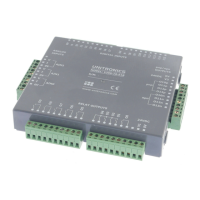
The V200-18-E1B
plugs directly into the back of
compatible Unitronics OPLCs,
creating a self-contained PLC unit
with a local I/O configuration.
Features
▪ 16 isolated digital inputs, including 2 high-speed counter inputs,
type pnp/npn (source/sink)
▪ 10 isolated relay outputs
▪ 4 isolated pnp/npn (source/sink) transistor outputs,
including 2 high-speed outputs
▪ 3 analog inputs
The Snap-in I/O plugs directly into the back of compatible Unitronics PLCs, creating a self-contained PLC unit with a local I/O configuration.
Detailed Installation Guides containing the I/O wiring diagrams for these models, technical specifications, and additional documentation are located
in the Technical Library in the Unitronics website: https://unitronicsplc.com/support-technical-library/
Alert Symbols and General Restrictions
When any of the following symbols appear, read the associated information carefully.
The identified danger causes physical and property damage.
The identified danger could cause physical and property damage.
▪ Before using this product, the user must read and understand this document.
▪ All examples and diagrams are intended to aid understanding, and do not guarantee operation. Unitronics accepts no responsibility for actual use
of this product based on these examples.
▪ Please dispose of this product according to local and national standards and regulations.
▪ Only qualified service personnel should open this device or carry out repairs.
▪ Failure to comply with appropriate safety guidelines can cause severe injury or property damage.
▪ Do not attempt to use this device with parameters that exceed permissible levels.
▪ To avoid damaging the system, do not connect/disconnect the device when power is on.
Environmental Considerations
▪ Do not install in areas with: excessive or conductive dust, corrosive or flammable gas,
moisture or rain, excessive heat, regular impact shocks or excessive vibration, in
accordance with the standards given in the product’s technical specification sheet.
▪ Do not place in water or let water leak onto the unit.
▪ Do not allow debris to fall inside the unit during installation.
▪ Ventilation: 10mm space required between controller’s top/bottom edges & enclosure walls.
▪ Install at maximum distance from high-voltage cables and power equipment.
The following section is relevant to Unitronics’ products that are listed with the UL.
The following models: V200-18-E1B, V200-18-E2B, V200-18-E6B, V200-18-E6BL are UL listed for Hazardous Locations.
The following models: V200-18-E1B, V200-18-E2B, V200-18-E3B, V200-18-E3XB, V200-18-E46B, V200-18-E46BL, V200-18-E4B, V200-18-E4XB,
V200-18-E5B, V200-18-E6B, V200-18-E6BL,
V200-18-ECB, V200-18-ECXB, V200-18-ESB are UL listed for Ordinary Location.
UL Ratings, Programmable Controllers for Use in Hazardous Locations,
Class I, Division 2, Groups A, B, C and D
These Release Notes relate to all Unitronics products that bear the UL symbols used to mark products that have been approved for use in hazardous
locations, Class I, Division 2, Groups A, B, C and D.
▪ This equipment is suitable for use in Class I, Division 2, Groups A, B, C and D, or Non-hazardous locations only.
▪ Input and output wiring must be in accordance with Class I, Division 2 wiring methods and in accordance with the authority having
jurisdiction.
▪ WARNING—Explosion Hazard—substitution of components may impair suitability for Class I, Division 2.
▪ WARNING – EXPLOSION HAZARD – Do not connect or disconnect equipment unless power has been switched off or the area is
known to be non-hazardous.
▪ WARNING – Exposure to some chemicals may degrade the sealing properties of material used in Relays.
▪ This equipment must be installed using wiring methods as required for Class I, Division 2 as per the NEC and/or CEC.
Relay Output Resistance Ratings
The products listed below contain relay outputs: V200-18-E1B, V200-18-E2B.
▪ When these specific products are used in hazardous locations, they are rated at 3A res, when these specific products are used in non-hazardous
environmental conditions, they are rated at 5A res, as given in the product’s specifications.