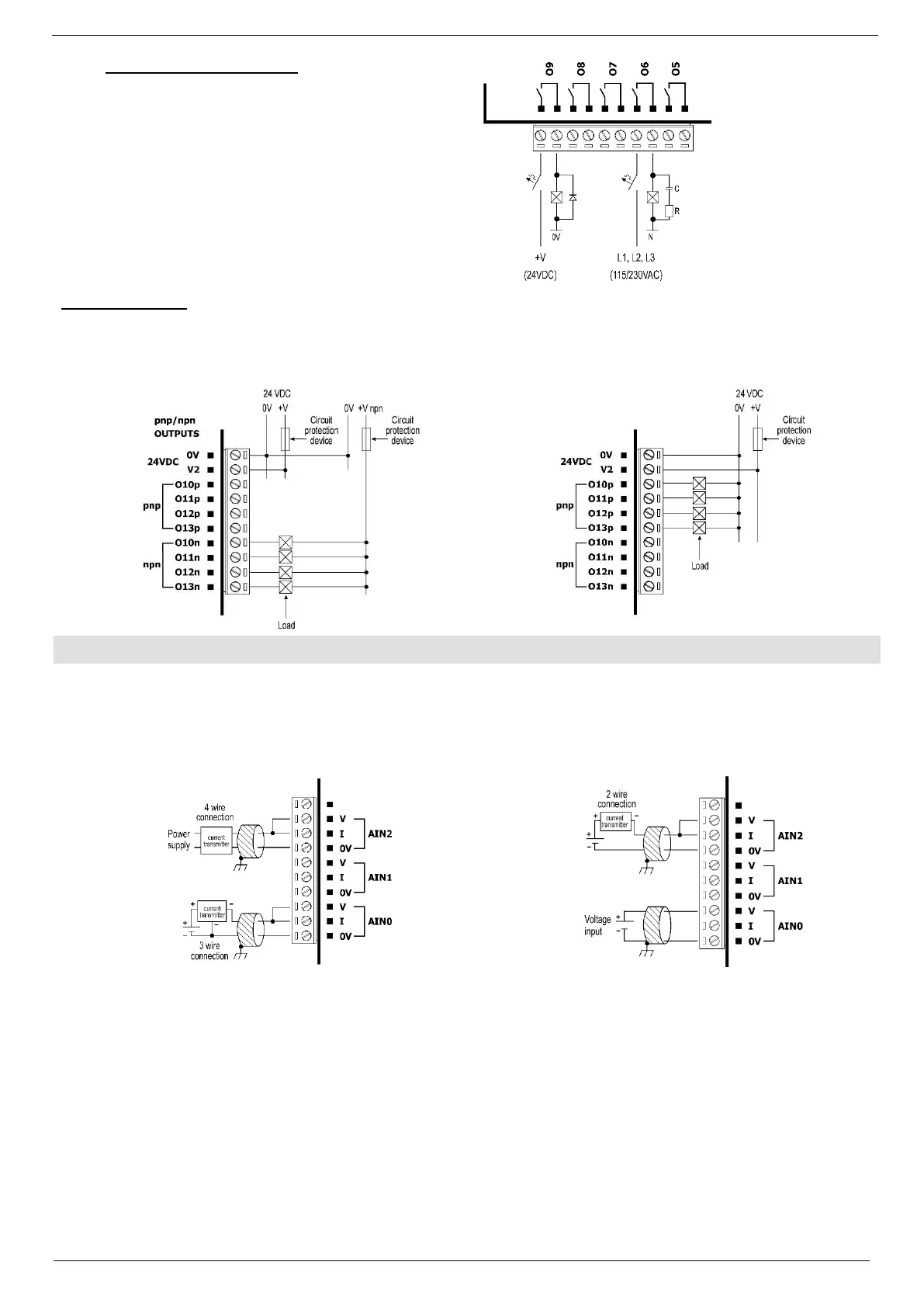
Increasing Contact Life Span
To increase the life span of the relay output
contacts and protect the device from potential
damage by reverse EMF, connect:
▪ a clamping diode in parallel with each
inductive DC load,
▪ an RC snubber circuit in parallel with each
inductive AC load.
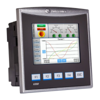
▪ Each output can be wired separately as either npn or pnp.
▪ The 0V signal of the transistor outputs is isolated from the controller’s 0V signal.
▪ Shields should be connected at the signal source.
▪ Inputs may be wired to work with either current or voltage.
▪ Note that the analog input’s 0V signal must be the same 0V used by the controller’s power supply.