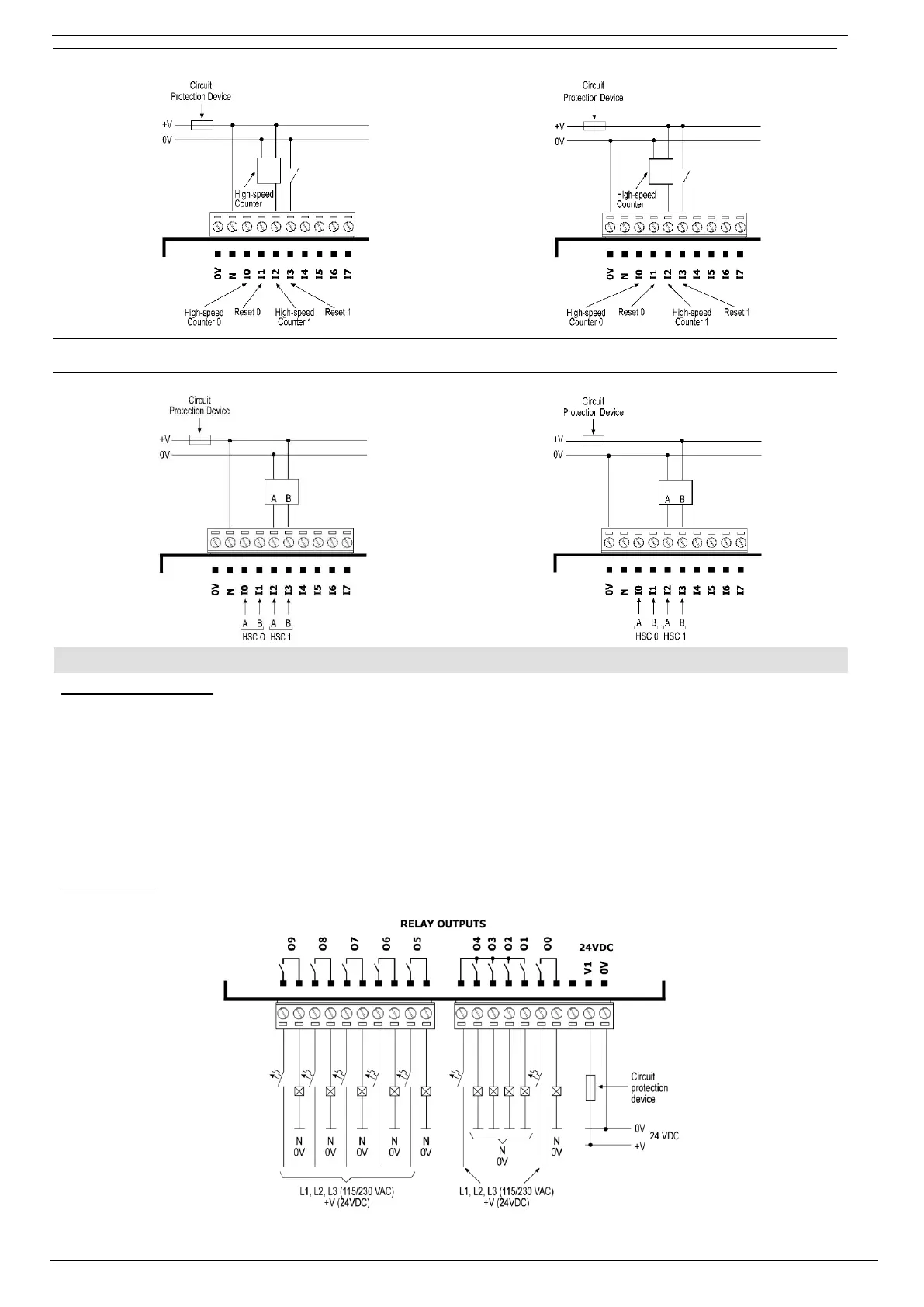
npn (sink) high-speed counter
pnp (source) high-speed counter
Inputs I0, I1, and I2, I3 can be used as shaft encoders as shown below.
npn (sink) shaft encoder wiring
pnp (source) shaft encoder wiring
1. Connect the "positive" lead to the “V1” terminal for the relay outputs, to the “V2” terminal for the transistor outputs.
2. In both cases, connect the “negative” lead to the “0V” terminal of each output group.
▪ In the event of voltage fluctuations or non-conformity to voltage power supply specifications, connect the device to a regulated power
supply.
▪ Do not connect the ‘Neutral’ or ‘Line’ signal of the 110/220VAC to the device’s 0V pin.
Relay Outputs
▪ The 0V signal of the relay outputs is isolated from the controller’s 0V signal.