EasyManua.ls Logo

Unitronics Vision V350-35-TR34 - User Manual

Unitronics Vision V350-35-TR34
10 pages
Print Icon
To Next Page IconTo Next Page
Loading...
Unitronics 1
Vision™ OPLC™
V350-35-TR34
Installation Guide
The Unitronics V350-35-TR34 offers the following onboard I/Os:
22 Digital Inputs, configurable via wiring to include 2 Analog and 3 HSC/Shaft-encoder Inputs
8 Relay Outputs, 4 high-speed npn Transistor Outputs
General Description
V350 OPLCs are micro-OPLCs, rugged programmable logic controllers that comprise:
On-board I/O configuration
Built-in operating panel containing a 3.5” Color Touchscreen and programmable function keys
Communications
1 built-in serial port: RS232/RS485
Optional: the user may order and install
one or both of the following modules:
- RS232/RS485/Ethernet
- CANbus
Communication Function Blocks
include: SMS, GPRS, MODBUS
serial/IP. Protocol FB enables PLC to
communicate with almost any external
device, via serial or Ethernet
communications
I/O Options
V350 supports digital, high-speed, analog,
weight and temperature measurement I/Os via:
On-board I/O configuration
Model-dependent
I/O Expansion Modules
Local or remote I/Os may be added via
expansion port or CANbus.
Information Mode
This mode enables you to:
View & Edit operand values, COM port settings, RTC and screen
contrast/brightness settings
Calibrate the touchscreen
Stop, initialize, and reset the PLC
To enter Information Mode, press the <i> button for several seconds.
Programming
Software,
& Utilities
The Unitronics Setup CD contains VisiLogic software and other utilities
VisiLogic
Easily configure hardware and write both HMI and Ladder control
applications; the Function Block library simplifies complex tasks
such as PID. Write your application, and then download it to the
controller via the programming cable included in the kit.
Utilities
Includes UniOPC server, Remote Access for remote programming
and diagnostics, and DataXport for run-time data logging.
To learn how to use and program the controller, as well as use utilities such
as Remote Access, refer to the VisiLogic Help system.
Question and Answer IconNeed help?

Do you have a question about the Unitronics Vision V350-35-TR34 and is the answer not in the manual?

Summary

General Description

Communication Features

Details built-in serial port (RS232/RS485) and optional Ethernet/CANbus modules.

I;O Options

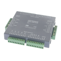
Covers support for digital, analog, weight, and temperature measurement I/Os via onboard/expansion modules.

Information Mode

Explains how to view/edit operands, COM settings, contrast, calibrate touchscreen, and reset the PLC.

Programming Software and Utilities

Covers VisiLogic for configuration and control, plus utilities like UniOPC server and Remote Access.

Mounting

Dimensions and Cutout

Provides physical dimensions and required panel cut-out specifications for installation.

Panel Mounting Instructions

Step-by-step guide for installing the controller into a panel using mounting brackets.

DIN-rail Mounting

Instructions for securely mounting the controller onto a standard DIN rail.

Wiring Guidelines

Wiring Procedure and Precautions

Details correct wire stripping, terminal connection, and general wiring safety precautions.

I;O Configuration and Wiring

Input Jumper Settings

Explains how to configure input functionality (digital, analog, HSC) using internal jumpers.

I;O Wiring Diagrams

Illustrates wiring for various input types (npn, pnp, HSC, shaft-encoder) and analog inputs.

Power Supply

Power Supply Wiring and Safety

Details power supply connections, including safe practices for 110/220VAC and regulated supplies.

Earthing the Power Supply

Provides instructions for grounding the power supply to maximize system performance and reduce interference.

Communication Ports

Communication Port Pinouts

Details the pin assignments for the RJ-11 communication port for RS232 and RS485.

RS232 to RS485 Jumper Settings

Explains how to change the communication standard and termination settings using internal jumpers.

Internal Configuration

Opening the Controller

Step-by-step instructions for safely opening the controller to access internal jumpers.

Changing I;O and Communication Settings

Guidance on modifying I/O and communication settings by adjusting internal jumpers.

Closing the Controller

Instructions for correctly reassembling the controller after internal adjustments.

Overview

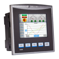
The Unitronics V350-35-TR34 is a micro-OPLC (Operator Panel Logic Controller), a rugged programmable logic controller that integrates an on-board I/O configuration with a built-in operating panel. This operating panel features a 3.5-inch color touchscreen and programmable function keys, providing a comprehensive solution for control and human-machine interface (HMI) applications.

Function Description:

The V350-35-TR34 is designed to manage a variety of control tasks through its versatile I/O capabilities and communication options. It supports digital, high-speed, analog, weight, and temperature measurement I/Os. The device can be expanded with additional local or remote I/O modules via an expansion port or CANbus, offering flexibility for various application sizes and complexities.

I/O Configuration:

The controller includes:

  • 22 Digital Inputs: These inputs are highly configurable. They can be wired as a group and set to either NPN (sink) or PNP (source) via a single jumper.
    • Inputs 14 and 15 can function as either digital or analog inputs.
    • Inputs 0, 2, and 4 can function as high-speed counters, as part of a shaft-encoder, or as normal digital inputs.
    • Inputs 1, 3, and 5 can function as either counter reset, as part of a shaft-encoder, or as normal digital inputs.
    • If inputs 0, 2, and 4 are set as high-speed counters (without reset), inputs 1, 3, and 5 can function as normal digital inputs.
  • 8 Relay Outputs: These outputs provide switching capabilities for various loads.
  • 4 High-Speed NPN Transistor Outputs: These outputs are suitable for applications requiring faster switching speeds.

Communication:

The V350-35-TR34 offers robust communication features:

  • Built-in Serial Port: One RS232/RS485 serial port is integrated.
  • Optional Modules: Users can order and install one or both of the following modules:
    • RS232/RS485/Ethernet module for enhanced connectivity.
    • CANbus module for industrial network communication.
  • Communication Function Blocks: The device supports various communication protocols including SMS, GPRS, MODBUS (serial/IP). A Protocol Function Block allows the PLC to communicate with almost any external device via serial or Ethernet.
  • RS232/RS485 Jumper Settings: The serial port can be configured for either RS232 or RS485 via jumpers. By default, the port is set to RS232 with termination ON. RS232 is used for program downloads from a PC and communication with serial devices like SCADA. RS485 enables the creation of a multi-drop network with up to 32 devices.

Usage Features:

  • Operating Panel: The integrated 3.5" Color Touchscreen and programmable function keys provide a user-friendly interface for monitoring and control.
  • Information Mode: This mode allows users to:
    • View and edit operand values.
    • Configure COM port settings.
    • Adjust Real-Time Clock (RTC) and screen contrast/brightness settings.
    • Calibrate the touchscreen.
    • Stop, initialize, and reset the PLC.
    • Information Mode is accessed by pressing the <i> button for several seconds.
  • Removable Memory Storage (Micro SD card): This feature allows for:
    • Storing datalogs, alarms, trends, and data tables.
    • Exporting data to Excel.
    • Backing up Ladder logic, HMI, and OS.
    • Cloning PLCs.
  • Data Tables: Enable setting recipe parameters and creating datalogs.
  • Programming Software (VisiLogic): The Unitronics Setup CD includes VisiLogic software, which allows users to:
    • Easily configure hardware.
    • Write both HMI and Ladder control applications.
    • Utilize a Function Block library for complex tasks like PID.
    • Download applications to the controller via the included programming cable.
  • Utilities: The Setup CD also includes:
    • UniOPC server.
    • Remote Access for remote programming and diagnostics.
    • DataXport for run-time data logging.
  • Mounting: The controller supports both panel mounting and DIN-rail mounting.
    • Panel Mounting: Requires a panel cut-out of 92 x 92 mm (3.622" x 3.622"). The mounting panel thickness should not exceed 5 mm. The controller slides into the cut-out with a rubber seal, secured by two mounting brackets.
    • DIN-rail Mounting: The controller snaps onto a standard DIN rail.

Maintenance Features:

  • Increasing Contact Life Span: To extend the life of relay output contacts and protect against reverse EMF, it is recommended to connect a clamping diode in parallel with each inductive DC load and an RC snubber circuit in parallel with each inductive AC load.
  • Opening the Controller: For accessing I/O jumpers or communication jumpers, the controller can be opened by removing four screws on the back cover.
    • Safety Precaution: Before opening, discharge any electrostatic charge by touching a grounded object. Avoid touching the PCB board directly; hold it by its connectors.
    • Procedure: Turn off power, disconnect, and dismount the controller. Remove the four corner screws from the back cover and pull it off.
  • Changing I/O Settings: Once the controller is open, the I/O board is exposed, allowing changes to I/O settings according to the jumper configurations detailed in the manual.
  • Changing Communication Settings: To access communication jumpers, the I/O PCB board needs to be steadily pulled off by its top and bottom connectors. Jumpers can then be changed as required.
  • Closing the Controller: Gently replace the board, ensuring pins fit correctly. Do not force the board. Replace the back cover and fasten the corner screws. The back cover must be securely replaced before powering up the controller.

Important Technical Specifications and Environmental Considerations:

  • Wiring:
    • Use crimp terminals for wiring with 26-12 AWG wire (0.13 mm²–3.31 mm²).
    • Strip wire to 7±0.5mm (0.250–0.300 inches).
    • Do not exceed a maximum torque of 0.5 N·m (5 kgf·cm) when tightening terminals to avoid wire damage.
    • Do not use tin, solder, or any substance on stripped wire that might cause the wire strand to break.
    • Input or output cables should not be run through the same multi-core cable or share the same wire.
    • Allow for voltage drop and noise interference with input lines over extended distances.
    • The controller and I/O signals must be connected to the same 0V signal.
  • Power Supply:
    • Install an external circuit breaker and use appropriate circuit protection devices.
    • Double-check all wiring before turning on the power supply.
    • A non-isolated power supply can be used if a 0V signal is connected to the chassis.
    • Do not connect the ‘Neutral’ or ‘Line’ signal of 110/220VAC to the device’s 0V pin.
    • In case of voltage fluctuations or non-conformity to power supply specifications, connect the device to a regulated power supply.
    • Earthing: Mount the controller on a metal panel. Connect one end of a 14 AWG wire to the chassis signal and the other end to the panel. The earthing wire should ideally not exceed 10 cm.
  • Environmental Conditions:
    • Do not install in areas with excessive or conductive dust, corrosive or flammable gas, moisture or rain, excessive heat, regular impact shocks, or excessive vibration, as specified in the product's technical specification sheet.
    • Ensure 10mm space between the controller's top/bottom edges and enclosure walls for ventilation.
    • Do not place in water or allow water to leak onto the unit.
    • Prevent debris from falling inside the unit during installation.
    • Install at maximum distance from high-voltage cables and power equipment.
  • Safety Guidelines:
    • Do not touch live wires.
    • Unused pins should not be connected, as this may damage the device.
    • Only qualified service personnel should open this device or carry out repairs.
    • Do not attempt to use this device with parameters exceeding permissible levels.
    • Do not connect/disconnect the device when power is on to avoid damaging the system.
    • The serial port is not isolated. If used with a non-isolated external device, avoid potential voltage exceeding ±10V.

Unitronics Vision V350-35-TR34 Specifications

General IconGeneral
BrandUnitronics
ModelVision V350-35-TR34
CategoryI/O Systems
LanguageEnglish

Related product manuals