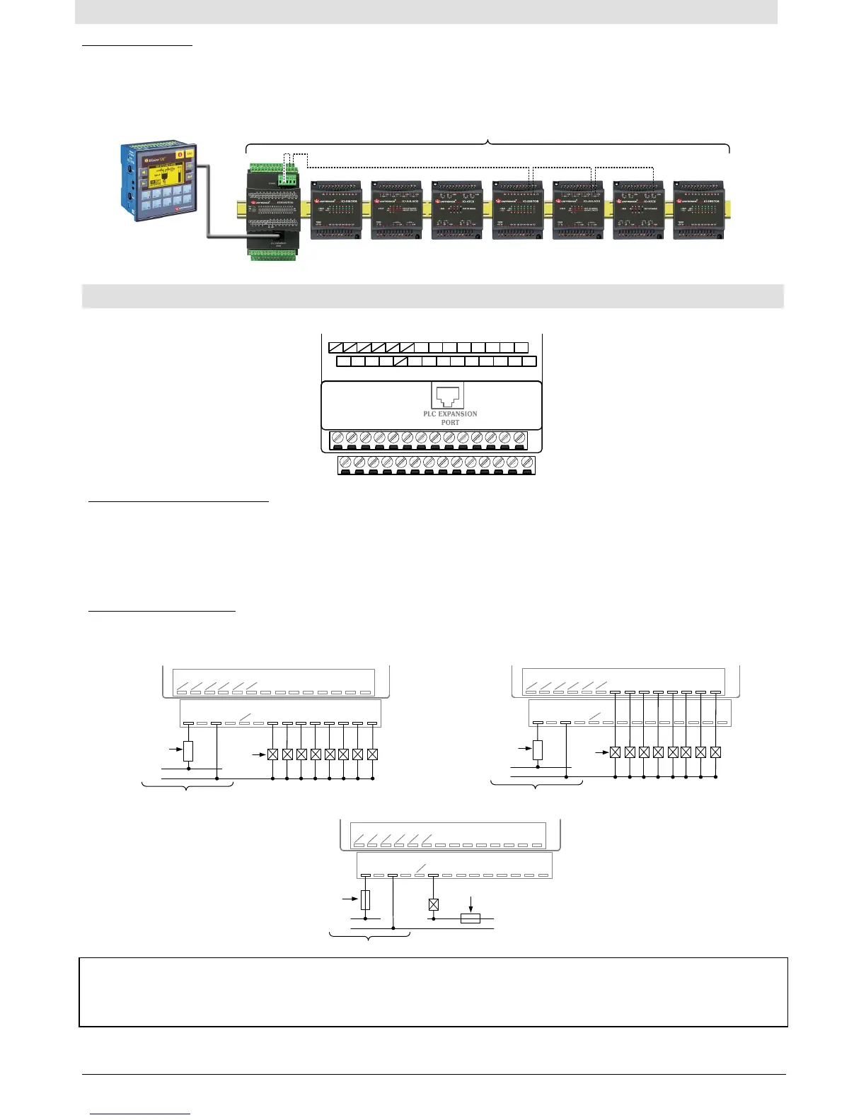
The following diagram shows the output connectors with pin numbers and corresponding output numbers.
+V +V 0V 0V
14 13 12 11 10 9 8 7 6 5 4 3 2 1
28 27 26 25 24
23 22 21 20 19 18 17 16 15
32 33 34 35 36 37 38 39
40 41 42 43 44 45 46 47
npn
pnp
32
Wiring the Output Power Supply
A non-isolated power supply can be used provided that the 0V signal is connected to the earth ground.
Do not connect the neutral or line signal of the 110/220VAC to the device’s 0V pin.
In the event of voltage fluctuations or non-conformity to voltage power supply specifications, connect the device to a
regulated power supply.
The adapter 0V and the I/O 0V must be connect to the same line, Ignoring this may damage the device.
Wiring Transistor Outputs
Output 32 can be wired either as pnp (source) or npn (sink). pnp and npn can be used simultaneously.
Output 32 can be used as a high speed output.
pnp (source) outputs 32-39
pnp (source) outputs 40-47
28 27 26 25 24
23 22 21 20 19 18 17 16 15
0V
+V
Output Power Supply
14 13 12 11 10 9 8 7 6 5 4 3 2 1
O32
O33
O34
O35
O36
O37
O38
O39
Circuit
Protection
Device
Load
+V
0V
28 27 26 25 24
23 22 21 20 19 18 17 16 15
0V
+V
Output Power Supply
14 13 12 11 10 9 8 7 6 5 4 3 2 1
O40
O41
O42
O43
O44
O45
O46
O47
Circuit
Protection
Device
Load
+V
0V
28 27 26 25 24
23 22 21 20 19 18 17 16 15
14 13 12 11 10 9 8 7 6 5 4 3 2 1
0V
+V
Output Power Supply
Circuit
Protection
Device
O0
Circuit Protection
Device
Load
0V
+V0
+V
0V
The information in this document reflects products at the date of printing. Unitronics reserves the right, subject to all app licable laws, at any time, at its sole discretion, and without notice, to discontinue or change the features, de signs,
materials and other specifications of its products, and to either permanently or temporarily withdraw any o f the forgoing from the market. All information in this document is provided "as is" without warranty of any kind, either expressed
or implied, including but not limited to any implied warranties of merchantability, fitness for a particular purpose, or non -infringement. Unitronics assumes no responsibility for errors or omissions in the information presented in
this document. In no event shall Unitronics be liable for any special, incidental, indirect or consequential damages of any kind, or any damages whatsoever arising out of or in connection with the use or performance of this information.
The tradenames, trademarks, logos and service marks p resented in this document, including their design, are the property of Unitronics (1989) (R"G) Ltd. or other third parties and you are not per mitted to use them without the prior
written consent of Unitronics or such third party as may own them.
DOC04000-A2 11-16
Connecting RG Pins
For correct operation of digital and analog inputs and for EMI immunity, connect the RG pin of all the expansion modules
containing RG signals to the adapter module 0V signal.
The overall length of the wire connecting the RG pins to the adapter 0V signal must be less than 3 meters.
Connect the RG pins in series (daisy chain). To facilitate this, use both the RG pins.
I/O Expansion Modules
0V
RG RG RG
0 1 5432 6
Expansion Module
(Built-in adapter)
7
RG
 Loading...