Do you have a question about the Unitronics Jazz JZ20-UA24 and is the answer not in the manual?
Specifications for unit dimensions, panel cut-out, and display viewable area.
Information about the built-in USB port, potentially used for programming.
Detailed instructions for DIN-rail and panel mounting procedures.
Step-by-step instructions for preparing and connecting wires to terminals.
Best practices for organizing and routing wires to ensure proper system operation.
Procedures for grounding the product to maximize performance and avoid interference.
Requirements for installing the device in ordinary locations according to UL standards.
Specific panel mounting instructions to meet UL hazardous location standards.
Guidelines for using USB and SD card slots, noting they are not for permanent connection.
Procedure and safety precautions for removing or replacing the device's battery.
Diagrams illustrating npn, pnp, and mixed wiring for digital inputs.
Information on the power supply connections for digital inputs.
Diagrams for connecting current-based analog inputs (2, 3, or 4 wire).
Diagrams for connecting voltage-based analog inputs.
Wiring details for thermocouple and PT100 sensor inputs, including wire colors.
Details on RTD types, ranges, resolution, and accuracy.
Details on thermocouple types, ranges, resolution, and accuracy.
Details on input voltage, permissible range, and current consumption.
Information on input type, number, voltage, current, and response time.
Specifications for relay and transistor outputs, including current and frequency.
Details on analog input/output ranges, impedance, resolution, and accuracy.
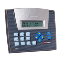
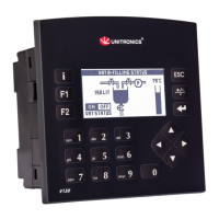
Variables for HMI display and communication protocols like GSM and MODBUS.
Details on the USB port for programming, communication, and add-on modules.
Information on using add-on modules for programming, modems, and networking.
| Brand | Unitronics |
|---|---|
| Model | Jazz JZ20-UA24 |
| Category | Controller |
| Language | English |