V200-18-E3XB Snap-in I/O Module 6/05
4 Unitronics
Digital Outputs
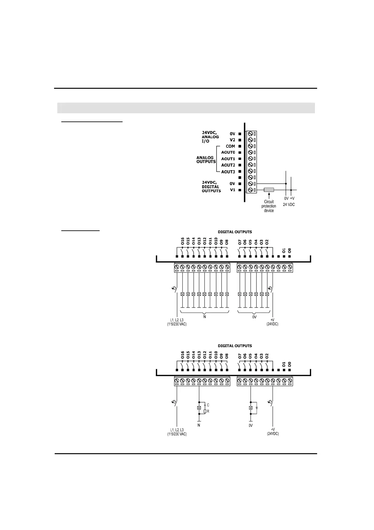
Wiring Power Supplies
Use a 24VDC power supply for both relay and
transistor outputs.
1. Connect the "positive" lead to the "V1"
terminal, and the “negative” lead to the "0V"
terminal.
In the event of voltage fluctuations or non-
conformity to voltage power supply
specifications,
connect the device to a regulated pow
er supply
Relay Outputs
Each output can be wired
separately to either AC or DC
as show
below
.
The 0V signal of the relay
outputs is isolated from the
controller’s 0V signal.
Increasing Contact Life Span
To increase the life span of the
relay output contacts and protect
the device from potential damage
by reverse EMF, connect:
a clamping diode in parallel
w
ith each inductive DC load,
an RC snubber circuit in
parallel w
ith each inductive AC
load.