6/05 V200-18-E3XB Snap-in I/O Module
Unitronics 5
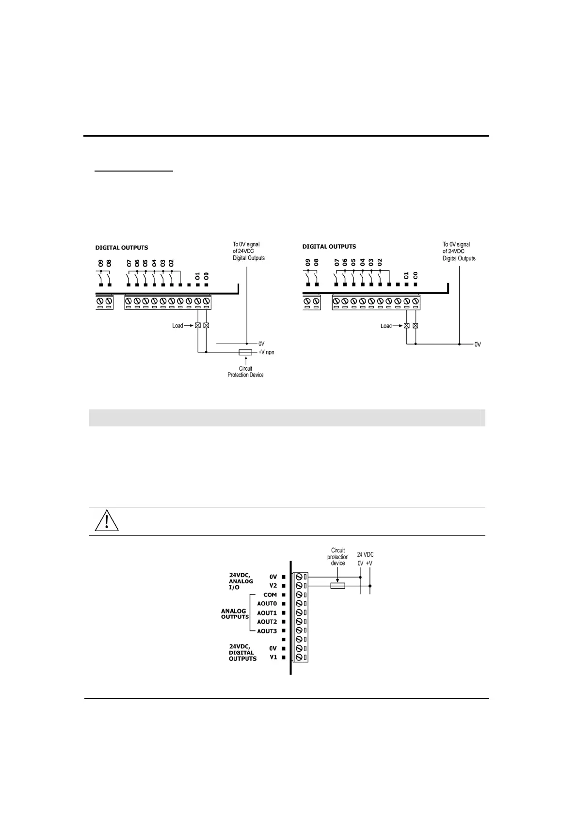
Transistor Outputs
Each output can function as either npn or pnp, in accordance with jumper settings and wiring. Open the
device and set the jumpers according to the instructions beginning on page 8.
The 0V signal of the transistor outputs is
isolated from the controller’s 0V signal.
npn (sink)
pnp (source)
Analog I/O Power Supplies
Use a 24VDC power supply for all analog input and output modes.
1.
Connect the "positive" cable to the "V2" term
inal, and the “negative” to the "0V" terminal.
In the event of voltage fluctuations or non-conformity to voltage power supply
specifications, connect the
device to a regulated pow
er supply.
Since the analog I/O power supply is isolated, the controller’s 24VDC power supply may
also be used to
power the analog I/Os.
The 24VDC pow
er supply must be turned on and off simultaneously with the controller’s
power supply.