EasyManua.ls Logo

Unitronics V570-57-T20B User Manual

Unitronics V570-57-T20B
8 pages
To Next Page IconTo Next Page
Page #1 background imageLoading...
Page #1 background image
Unitronics 1
Vision™ OPLC™
Installation Guide
V570-57-T20B and V570-57-T40B
This guide provides basic information for Unitronics’ controllers V570-57-T20B and V570-57-T40B.
General Description
Vision OPLCs are programmable logic controllers that comprise an integral operating panel.
V570-57-T20B and V570-57-T40B comprise a color touchscreen, which displays a virtual keyboard
when the application requires the operator to enter data.
Communications 2 isolated RS232/RS485 ports
Isolated CANbus port, CANopen & UniCAN
The user can order and install an Ethernet port
Communication Function Blocks include: SMS, GPRS, MODBUS
serial/IP Protocol FB enables PLC to communicate with almost any
external device, via serial or Ethernet communications
I/O Options Vision supports up to 512
1
digital,
high-speed, and analog I/Os via:
Snap-in I/O Modules
Plug into the back of the
controller to provide an on-
board I/O configuration
I/O Expansion Modules
Via adaptor, local or remote
I/Os may be added via
expansion port or CANbus
Installation instructions and other data may be found in the module’s technical
specification sheet.
Information Mode This mode enables you to:
Calibrate the touchscreen
View & Edit operand values, COM port settings, RTC and screen
contrast/brightness settings
Stop, initialize, and reset the PLC
To enter Information Mode, press the touchscreen and maintain contact for
several seconds.
Programming
Software,
& Utilities
The Unitronics Setup CD contains VisiLogic software and other utilities
VisiLogic
Easily configure hardware and write both HMI and Ladder control
applications; the Function Block library simplifies complex tasks
such as PID. Write your application, and then download it to the
controller via the programming cable included in the kit.
Utilities
These include UniOPC server, Remote Access for remote
programming and diagnostics, and DataXport for run-time data
logging.
To learn how to use and program the controller, as well as use utilities such as
Remote Access, refer to the VisiLogic Help system.
1
Number of I/Os may vary according to I/O module selection.
Question and Answer IconNeed help?

Do you have a question about the Unitronics V570-57-T20B and is the answer not in the manual?

Unitronics V570-57-T20B Specifications

General IconGeneral
BrandUnitronics
ModelV570-57-T20B
CategoryNetwork Router
LanguageEnglish

Summary

Product General Description

Communication Ports and Protocols

Details communication ports like RS232/RS485 and CANbus, plus communication blocks.

I/O Module Options

Covers Snap-in and Expansion I/O Modules for expanding digital, high-speed, and analog I/Os.

Information Mode Operation

Explains how to enter Information Mode for calibration, viewing/editing operands, and PLC control.

Programming Software and Utilities

Introduces VisiLogic software for HMI/Ladder applications and utilities like UniOPC server.

Memory and Data Storage Capabilities

Removable Memory Storage Options

Explains using SD cards for datalogs, backups, and cloning PLCs.

Operand Types and Data Table Capacities

Lists available operand types and the capacity for dynamic and fixed data.

Standard Kit Components

Safety and Precautions

Danger Symbols and Safety Warnings

Highlights danger, warning, and caution symbols and their meanings for safe operation.

Environmental Installation Considerations

Outlines conditions to avoid for installation, such as dust, moisture, and extreme temperatures.

Battery Installation Procedure

Controller Physical Dimensions

Panel Mounting Instructions

Panel Cut-out and Mounting Steps

Guides on creating a panel cut-out and securely mounting the controller using brackets.

Controller Interface and Port Identification

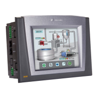
Identifies key ports and connectors on the controller for connectivity.

Wiring and Power Supply Guidelines

General Wiring Safety and Best Practices

Provides critical wiring precautions, including wire stripping and terminal connection.

Power Supply Voltage and Ripple Requirements

Details the 24VDC power supply specifications, including voltage range and ripple.

Power Supply Earthing Procedure

Explains the procedure for earthing the power supply to enhance system performance and reduce interference.

Communication Port Configuration

Serial Port RS232/RS485 Configuration

Explains how to set serial ports to RS232 or RS485 using DIP switches.

RS232/RS485 Port Pinouts

Provides pinout details for RS232 and RS485 communication ports.

COM Port DIP Switch Settings

Details the DIP switch settings for configuring COM1 and COM2 for RS232 or RS485.

Snap-in I/O Module Management

Removing the Snap-in I/O Module

Describes the steps to safely remove a Snap-in I/O Module from the controller.

Re-installing the Snap-in I/O Module

Guides on correctly aligning and securing a Snap-in I/O Module back onto the controller.

CANbus Network Configuration

CANbus Protocols and Network Usage

Explains CANbus port usage for decentralized networks and supported protocols like CANopen.

CANbus Wiring and Network Termination

Details the recommended wiring, cable type, and terminator placement for CANbus networks.

CANbus Connector Pinout Details

Illustrates the pin configuration for the CANbus connector, including power and signal lines.

Related product manuals