Do you have a question about the Universal Audio LA-2A and is the answer not in the manual?
Do not use the unit near water or in excessively moist environments.
Prevent objects from falling into or liquids from spilling into the unit through openings.
Ensure adequate ventilation to prevent overheating and damage to the unit.
Position the unit away from heat sources or other equipment that produces heat.
Connect the unit to a power supply only of the type described or marked on the unit.
Route AC power cords to prevent them from being walked on or pinched.
Use the 3-wire grounding plug only in a grounding-type power outlet for safety.
Use only manufacturer-recommended carts or stands and move with care to prevent tipping.
Mount the unit to a wall or ceiling only as recommended by the manufacturer.
Clean the unit only as recommended by the manufacturer.
Unplug the AC power cord from the outlet when the unit is left unused for a long period.
Refer to qualified personnel for damage like cord issues, liquid spills, or abnormal operation.
Do not attempt user servicing beyond operating instructions; refer all servicing to qualified personnel.
Specifies the maximum gain reduction capability, up to 40 dB.
Details harmonic distortion limits at specified output levels (+10dBm and +16dBm).
Outlines the frequency response range, +/- 0.1 dB from 30 cycles to 15 kilocycles.
States the noise floor relative to the output level, 75 dB below +10 dBm.
Defines the gain range, specified as 40 +/- 1dB.
Indicates nominal and peak output levels, +10dBm and +16dBm respectively.
Specifies the maximum allowable input signal level, +16 dBm.
Describes the attack time as very fast.
Details release time characteristics: 0.06s for 50% release, 0.5-5s for full release.
Specifies the input impedance as 600 ohms balanced.
Specifies the output impedance as 600 ohms balanced.
Provides the physical size of the panel, 19" x 5 ¼".
States the required depth behind the panel, 7 ½”.
Lists the main controls: Gain (Output level), Peak Reduction, and Meter Selector Switch.
Describes meter functions: dB Gain Reduction and dB Output.
Lists the vacuum tubes used: (2) 12AX7A, (1) 12BH7A, (1) 6AQ5.
Details how to make audio connections using XLR connectors and terminal strips for input/output.
Provides instructions for using barrier strip connections as an alternative to XLRs.
Explains the function of the Peak Reduction control for setting the desired amount of compression.
Describes how to adjust the output level after the compression amount is set.
Explains the VU meter's modes for output level (+4/+10 dB) and gain reduction monitoring.
Details how the switch affects the compressor's IO curve, changing the compression ratio.
Instructions for zeroing the meter in Gain Reduction mode using a potentiometer.
Explains the R37 control for adjusting high-frequency compression sensitivity for broadcast.
Details interconnecting two units for stereo and calibrating gain reduction balance between them.
Explains fundamental compressor principles, input/output curves, and terminology like ratio and threshold.
Presents a functional overview of the LA-2A's internal signal flow and key component interactions.
Details the side-chain's role in controlling gain reduction via voltage control and equalization.
Describes the output stage, including the voltage amplifier and cathode follower stages.
Explains the three modes of the LA-2A's metering system for output and gain reduction.
Discusses the classic status and enduring popularity of the 1176 and LA-2A compressors in studios.
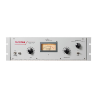
Provides historical context, technical features, and original production details of the LA-2A.
Details Bill Putnam's design process for the 1176, including challenges and innovations.
Features testimonials from engineers on the sonic impact and usage of the 1176 and LA-2A.
| Output Impedance | 600 ohms |
|---|---|
| Type | Optical Compressor/Limiter |
| Gain | 40 dB |
| Frequency Response | 30 Hz to 15 kHz |
| Input Impedance | 600 ohms |
| Compression Ratio | Variable, program dependent |
| Attack Time | 10 milliseconds |
| Release Time | 50 ms - 5 sec (program dependent) |
| Power Requirements | 115/230 VAC, 50/60 Hz |
| THD | <0.5% at +10 dBm output |
| Metering | VU meter |
| Total Harmonic Distortion | <0.5% at +10 dBm output |
| Maximum Input Level | +16 dBu |
| Tubes | 2x 12AX7 |
| Dimensions | 19" |