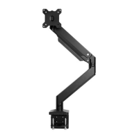
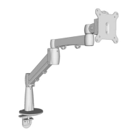
4
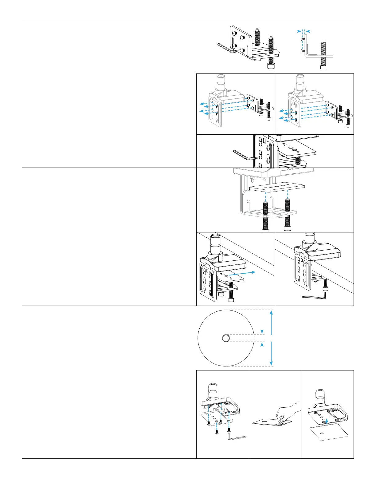
Step 4 (Clamp Method)
A. Use the 4mm Allen Wrench to adjust the four pre-
installed screws on the back of the Lower Clamp so
that there are about 0.25” of thread between the plate
and screw heads.
B. Insert the four screws of the Lower Clamp through four
of the key slot holes in the back of the Upper Clamp as
shown. There are two sets of key slot holes to choose
from for different desktop thicknesses.
• For Desks 0.4” to 2.25” use the top four key slot holes
(g. 1)
• For Desks 2” to 3.3” use the bottom four key slot
holes (g. 2)
C. Slide the Lower Clamp assembly down so that the
screws are at the bottom of the key slot holes then
tighten screws with 4mm Allen Wrench.
g. 2
.25”
g. 1
Step 6 (Bolt-Through Method)
Ensure the desktop has a hole between 0.4’’ and 3.1’’ in
diameter to use this option. Using a grommet hole that
is already in your desktop is acceptable, or you can drill a
0.5” hole anywhere on your desktop.
Step 5 (Clamp Method)
A. Using the 6mm Allen Wrench, adjust both bolts on the
bottom of the Lower Clamp so that the opening is wide
enough to accommodate the thickness of the desktop
and Lower Base Plate.
B. Place the outer holes of the Lower Base Plate onto the
tips of the bolts as shown.
C. Slide the assembly onto the back of the desktop,
then tighten the bolts using the 6mm Allen Wrench.
Alternate from one bolt to the other, to allow the Lower
Base Plate to rise evenly before nally tightening to the
desktop.
D. If you chose the Clamp Method for mounting, please
skip the Bolt-Through Method Steps 6-9 and proceed
with Step 10.
Step 7 (Bolt-Through Method)
A. Align the Upper Base Plate with the Base in the
orientation shown and attach it using the four M6 x 12
Flathead Screws and the 4mm Allen Wrench.
B. Then peel the adhesive backing off of the Adhesive Pad
and attach it to the bottom of the Base and Upper Base
Plate as shown. Align the pad with the front edge of the
Base rst, then work to the back.
.4”
3.1”
 Loading...